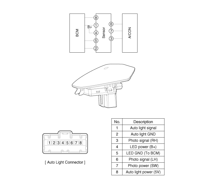
Kia Optima Hybrid: Auto Lighting Control System / Schematic Diagrams
| Circuit Diagram |

 Components and Components Location
Component Location 1. Auto light sensor2. Head lamps3. Lighting switch (Auto)4. Tail lamps5. Body control module (BCM) ...
 Auto Light Switch Repair procedures
Inspection Lighting Switch Inspection With the multi function switch in each position, make sure that continuity exists between the terminals below. If continuity is not as specified, replace the multi-function ...
Other information:
Kia Optima Hybrid (TF HEV) 2016-2020 Service Manual: General Safety Information and Caution
Safety Precaution Since hybrid vehicles contain a high voltage battery, if the high voltage system or vehicles are handled incorrectly, this might lead to a serious accidents like electric shock and electric leakage. • Be sure to shut off the high voltage by removing the ...
Kia Optima Hybrid (TF HEV) 2016-2020 Service Manual: Special Service Tools
Special Service Tools Tool Name / NumberIllustrationDescriptionBand installer09495 - 39100Installation of hook type boot band.Band installer09495 - 3K000Installation of ear type boot bandLower arm ball joint remover0K545-A9100Removal of front lower arm from front axle Personal Protective Equipment NameIllustrationDescriptionInsulation ...
