Kia Optima Hybrid: Horn / Repair procedures
| Inspection |
| 1. |
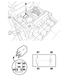
Remove the horn relay (A) from the engine room relay box. |
| 2. |
There should be continuity between the No.30 and No.87
terminals when power and ground are connected to the No.85 and No.86
terminals. |
| 3. |
There should be no continuity between the No.30 and No.87 terminals when power is disconnected.
|
| Removal |
| 1. |
Remove the front bumper.
(Refer to the BD group - "Front bumper") |
| 2. |
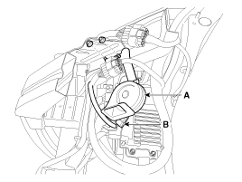
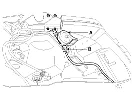
Remove the mounting nut and disconnect the horn connector (B), then remove the horn (A).
|
| Installation |
| 1. |
Connect the horn connector, then reassemble the horn. |
| 2. |
Reassemble the front bumper. |
 Components and Components Location
Component Location 1. Horn switch2. Horn relay (Engine room compartment)3. Horn (Low)4. Clock spring5. Horn (High) ...
 AVN System
...
Other information:
Kia Optima Hybrid (TF HEV) 2016-2020 Service Manual: Description and Operation
Description system outline An optimal seat position set by a driver can be memorized in Power seat unit by IMS SW, which enables restoration of seat position set by the driver despite Playing of this function during drive is banned for safety reasons, and it has emergency stop function of restoration ...
Kia Optima Hybrid (TF HEV) 2016-2020 Service Manual: Engine Control Module (ECM) Schematic Diagrams
ECM Terminal And Input/Output signal ECM Terminal Function Connector [C100-K] PinNo.DescriptionConnected to1Power groundChassis Ground2Battery power (B+)Ignition Switch3Power groundChassis Ground4Battery power (B+)Main Relay5Power groundChassis Ground6Battery power (B+)Battery 7-8-?9Fuel Level Sender ...


