Kia Optima Hybrid: Parking Assist System / Rear Parking Assist System Switch Repair procedures
| Removal |
| 1. |
Disconnect the negative (-) battery terminal. |
| 2. |
Remove the smart junction box cover. |
| 3. |
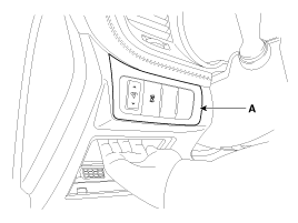
Remove the crash pad side switch assembly (A) as shown below picture.
|
| 4. |
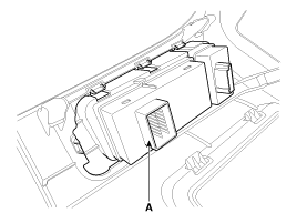
Remove the PAS switch (A) after disconnecting the connector.
|
| Installation |
| 1. |
Install the PAS switch and crash pad switch assembly. |
| 2. |
Connect the negative (-) battery terminal. |
| Inspection |
| 1. |
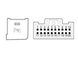
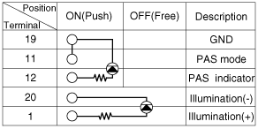
Check for continuity between the terminals while operate the PAS switch.
|
 Parking Assist Sensor Repair procedures
Removal 1. Disconnect the negative (-) battery terminal. 2. Remove the front/rear bumper. (Refer to Body - "Front Bumper cover") (Refer to Body - "Rear Bumper cover") 3. Disconnect the connector (A) from ...
Other information:
Kia Optima Hybrid (TF HEV) 2016-2020 Service Manual: Description and Operation
Description Regeneration Brake System During deceleration or braking of an electric vehicle or HEV, the drive motor acts as an alternator and charges the battery by converting the vehicle’s kinetic energy generated during braking into electrical energy. Regenerative braking amount depends on the vehicle ...
Kia Optima Hybrid (TF HEV) 2016-2020 Service Manual: Power Door Lock Switch Repair procedures
Inspection Driver Door Lock Switch Inspection 1. Disconnect the negative (-) battery terminal. 2. Remove the front door trim panel. (Refer to the BD group - "Front door") 3. Disconnect the connector from the power window switch module. 4. Check for continuity between the terminals in each switch position ...


