Kia Optima Hybrid: AHB(Active Hydraulic Boost) System / Description and Operation
Kia Optima Hybrid (TF HEV) 2016-2020 Service Manual / Brake System / AHB(Active Hydraulic Boost) System / Description and Operation
| Description |
| Regeneration Brake System |
During deceleration or braking of an electric vehicle or HEV,
the drive motor acts as an alternator and charges the battery by
converting the vehicle’s kinetic energy generated during braking into
electrical energy.
Regenerative braking amount depends on the vehicle speed, battery SOC, etc.
Achieves significant improvement in fuel efficiency in city driving with repeated acceleration and deceleration.
| Regenerative Braking Cooperation Control (RBC) |
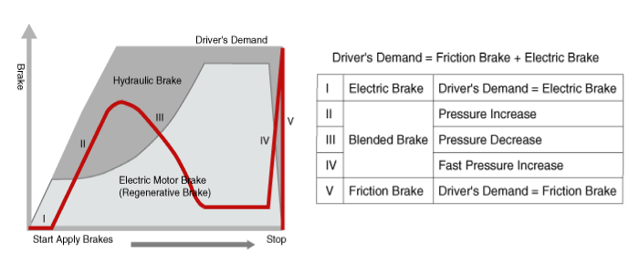
The brake force apportion is distributed by controlling
hydraulic braking and the total brake force (hydraulic + regenerative
brake) output that the driver requires is generated.In the case of
regenerative brake failure, the total brake force that the driver
requires is supplied by the hydraulic brake system.
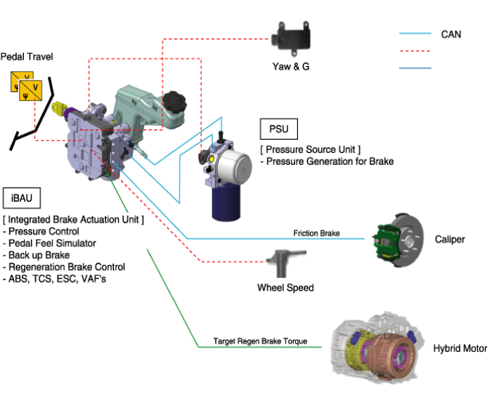
The AHB system is composed of the Pressure Source Unit (PSU), the Intergrated Brake Actuation Unit (IBAU).
First, the PSU generates the hydraulic pressure required for braking.
Similar to the boosting effect when the driver steps on the
brake pedal in a system equipped with a vacuum booster, the hydraulic
pressure stored in the cylinder is supplied to provide pressure
throughout the entire brake line.
Second, the IBAU delivers pressure that is generated by the
PSU to a caliper on each wheel. It is connected to the brake pedal to
detect the brake force that is required by the driver, and to generate a
brake feeling.
The IBAU carries out the ABS, TCS, and ESC functions as in conventional vehicles.
| AHB System Operation Principals |
| 1. Initial Status |
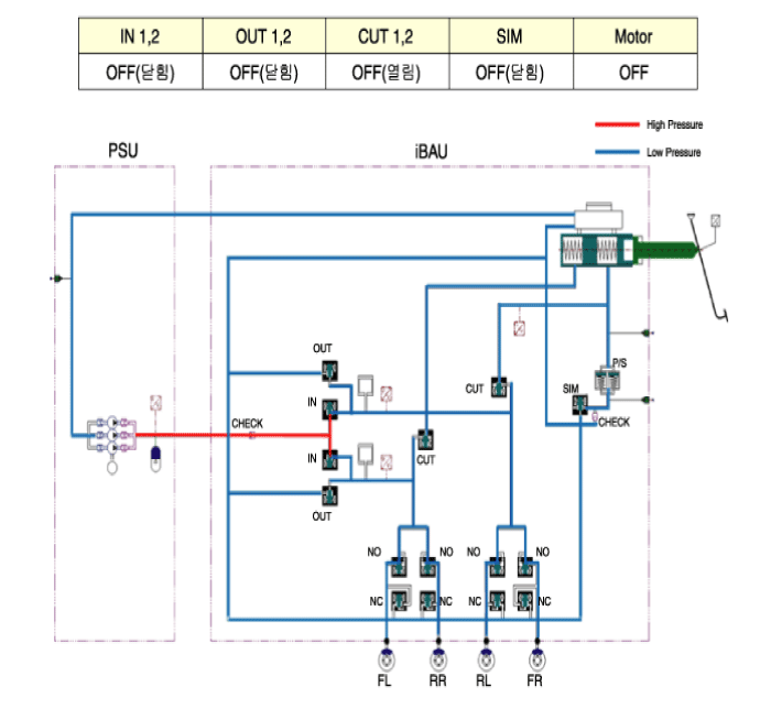
High pressure (180 bar) between the PSU and the IBAU is
generated consistently. Therefore, before removing the PSU or the IBAU,
high pressure between them should be reduced for safety by conducting
"High pressure release mode" of GDS connected to TF HEV.
| 2. Brake operation |
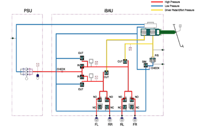
Apply Mode : During normal braking, IN valve becomes ON and
opens; then, the high pressure generated by PSU is supplied to a caliper
on each wheel by IBAU and the brake operation is engaged.
Level of brake force is decided by the pedal simulater with
conducting measurement of the pedal stroke sensor. Release Mode : During
discharging brake, OUT valve opens and IN valve closes; then, the high
pressure of brake oil return back to PSU. At this time, CUT valve is ON
and it prevents back flow of brake oil to IBAU. |
| 2. Brake malfunction |
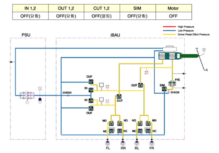
If the PSU or the IBAU is broken, IN valve and OUT valve are
closed, and CUT valve is off. Therefore, the brake force is generated by
only pressing a brake pedal manually by a driver.
| Active Hydraulic Boost Circuit Diagram (1) |
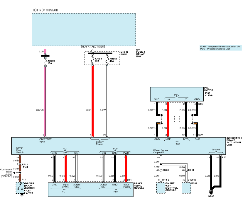
| Active Hydraulic Boost Circuit Diagram (2) |
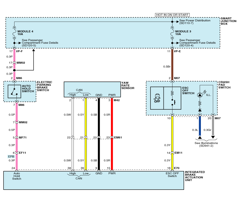
| Active Hydraulic Boost Circuit Diagram (3) |
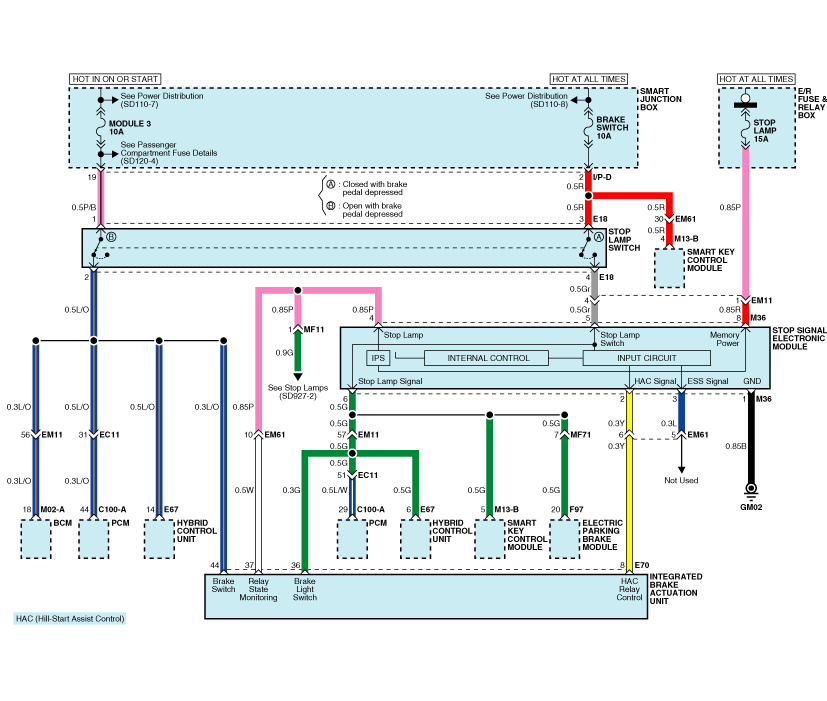
| Active Hydraulic Boost Circuit Diagram (4) |
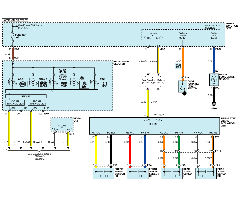
| IBAU connector input/output |

| Description | Description | ||||
| 1. | R | E/R Fuse & Relay Box (Multi Fuse - AHB 1) | 24. | P | Electric Parking Brake Switch (Auto Hold Swutch) |
| 2. | R | PSU Motor (+) | 25. | - | - |
| 3. | - | - | 26. | - | - |
| 4. | B/O | PSU Motor (GND) | 27. | G | Rear Wheel Sensor LH (SIG) |
| 5. | P/B | E/R Fuse & Relay Box (Fuse - AHB 3) | 28. | B | Front Wheel Sensor LH (SIG) |
| 6. | R | Brake Pedal Module (PDT PWR) | 29. | L | Driver Door Switch |
| 7. | R | Brake Pedal Module (PDF PWR) | 30. | W | E/R Fuse & Relay Box (Multi Fuse - AHB 2) |
| 8. | L | Stop Signal Electronic Module | 31. | B | Brake Pedal Module (PDF GND) |
| 9. | B | Yaw Rate Sensor (GND) | 32. | - | - |
| 10. | B | Brake Pedal Module (PDT GND) | 33. | O | Rear Wheel Sensor LH (VCC) |
| 11. | B/O | PSU Motor (GND) | 34. | W | Rear Wheel Sensor RH (VCC) |
| 12. | - | - | 35. | - | - |
| 13. | B | PSU Motor (-) | 36. | G | Stop Signal Electronic Module |
| 14. | B | Ground (GE06) | 37. | W | Stop Signal Electronic Module |
| 15. | R | Yaw Rate Sensor (PWR) | 38. | W | Yaw Rate Sensor (CAN - High) |
| 16. | Y | Crash Pad Switch (ESC OFF Switch) | 39. | Y | Yaw Rate Sensor (CAN - Low) |
| 17. | Y | Front Wheel Sensor LH (VCC) | 40. | W | Vehicle Speed : Smart Key Control Module, PCM |
| 18. | R | Front Wheel Sensor RH (VCC) | 41. | - | - |
| 19. | W | C-CAN (High) | 42. | L | Front Wheel Sensor RH (SIG) |
| 20. | Br | C-CAN (Low) | 43. | O/B | Rear Wheel Sensor RH (SIG) |
| 21. | - | - | 44. | L/O | Stop Lamp Switch |
| 22. | W | Brake Pedal Module (PDT SIG) | 45. | - | - |
| 23. | Gr | Brake Pedal Module (PDF SIG) | 46. | B | Ground (GE06) |
| Operation and Leakage Check |
Check all of the following items:
| Component | Procedure |
| Integrated Brake Actuation Unit (IBAU) (A) and Pressure Source Unit (PSU) (B) | Check
brake operation by applying the brakes during a test drive. If the
brakes do not work properly, check the IBAU and PSU. Replace IBAU and
PSU as an assembly if it does not work properly or if there are signs of
leakage. |
| Piston cup and pressure cup inspection (B) | Check
brake operation by applying the brakes. Look for damage or signs of
fluid leakage. Replace the IBAU as an assembly if the pedal does not
work properly or if there is damage or signs of fluid leakage. |
| Brake hoses (C) | Look for damage or signs of fluid leakage. Replace the brake hose with a new one if it is damaged or leaking. |
| Caliper piston seal and piston boots (D) | Check brake operation by applying the brakes. Look for damage or signs of fluid leakage. If the pedal does not work properly, the brakes drag, or there is damage or signs of fluid leakage, disassemble and inspect the brake caliper. Replace the boots and seals with new ones whenever the brake caliper is disassembled. |
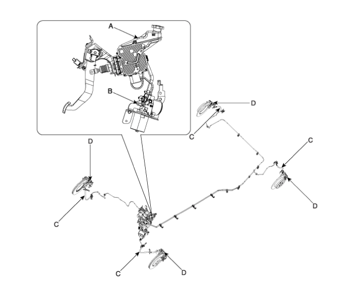
 Brake Actuation Unit Components and Components Location
Components IBAU must not be disassembled. 1. ECU2. Reservoir3. Master cylinder Assembley 4. Valve block ...
Other information:
Kia Optima Hybrid (TF HEV) 2016-2020 Service Manual: Driver Airbag (DAB) Module and Clock Spring Description and Operation
Description Driver Airbag (DAB) is installed in the steering wheel and electrically connected to SRSCM via the clock spring. It protects the driver by deploying the airbag when frontal crash occurs. The SRSCM determines deployment of the Driver Airbag (DAB). Never attempt to measure the ...
Kia Optima Hybrid (TF HEV) 2016-2020 Service Manual: Climate Control Air Filter Repair procedures
Replacement 1. Disconnect the damper (B) from the glove box (A).Remove the glove box lift (C). 2. Remove the filter cover with pushing the knob. 3. Replace the air filter (B), install it after making sure of the direction of air filter. In case of driving in an air-polluted area or rugged ...
© 2025 Copyright www.koptimatfhev.com


