Kia Optima Hybrid: Seat Electrical / Power Seat Control Switch Repair procedures
Kia Optima Hybrid (TF HEV) 2016-2020 Service Manual / Body Electrical System / Seat Electrical / Power Seat Control Switch Repair procedures
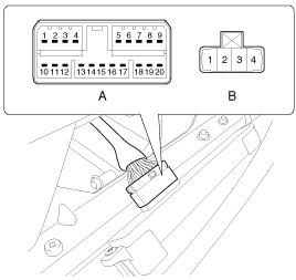
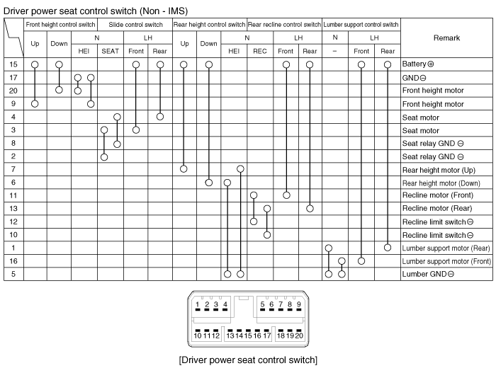
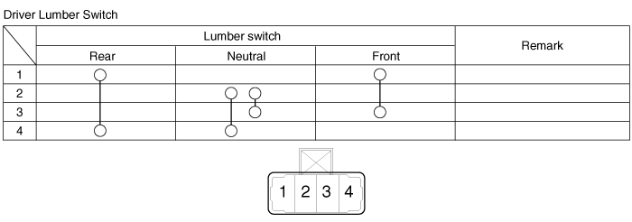
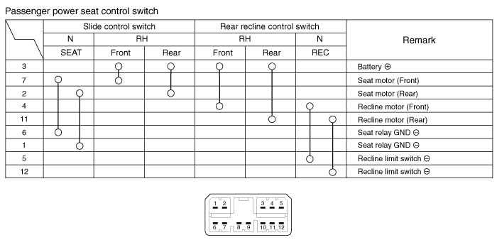
| Inspection |
With the power seat switch in each position, make sure that
continuity exists between the terminals below. If continuity is not as
specified, replace the power seat switch.
A : Power seat control switch
B : Lumber support switch
| Removal |
| 1. |
Disconnect the negative (-) battery terminal. |
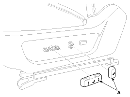
| 2. |
Remove the seat control switch (A).
|
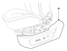
| 3. |
Remove the seat side cover (A).
(Refer to the BD group - "Front seat")
|
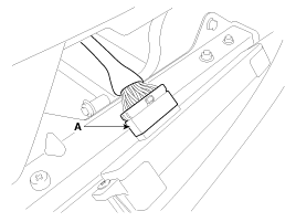
| 4. |
Disconnect the power seat control switch connector (A).
|
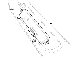
| 5. |
Remove the power seat control switch (A) after removing the mounting screws (3EA).
|
| Installation |
|

| 1. |
Connect the connectors and reassemble the IMS control switch. |
| 2. |
Reassemble the seat side cover. |
 Power Seat Control Switch Schematic Diagrams
Circuit Diagram ...
 Seat Heater Switch Schematic Diagrams
Circuit Diagram ...
Other information:
Kia Optima Hybrid (TF HEV) 2016-2020 Service Manual: General Safety Information and Caution
Safety Precaution Since hybrid vehicles contain a high voltage battery, if the high voltage system or vehicles are handled incorrectly, this might lead to a serious accidents like electric shock and electric leakage. • Be sure to shut off the high voltage by removing the ...
Kia Optima Hybrid (TF HEV) 2016-2020 Service Manual: Engine Coolant Temperature Sensor (ECTS) Description and Operation
Description Engine Coolant Temperature Sensor (ECTS) is located in the engine coolant passage of the cylinder head for detecting the engine coolant temperature. The ECTS uses a thermistor whose resistance changes with the temperature. The electrical resistance of the ECTS decreases as the temperature ...
© 2025 Copyright www.koptimatfhev.com