Kia Optima Hybrid: Heater / Mode Control Actuator Repair procedures
| Inspection |
| 1. |
Ignition "OFF” |
| 2. |
Disconnect the connector of mode control actuator. |
| 3. |
Verify that the mode control actuator operates to the defrost
mode when connecting 12V to the terminal 3and grounding terminal 7. |
| 4. |
Verify that the mode control actuator operates to the vent mode when connecting in the reverse.
|
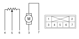
| 5. |
Check the voltage between terminals 5 and 6.
Specification
It will feedback current position of actuator to controls. |
| 6. |
If the measured voltage is not specification, substitute with a known-good mode control actuator and check for proper operation. |
| 7. |
If the problem is corrected, replace the mode control actuator. |
| Replacement |
| 1. |
Disconnect the negative (-) battery terminal. |
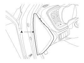
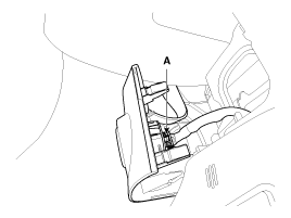
| 2. |
Using the screwdriver, remove the side cover (A).
|
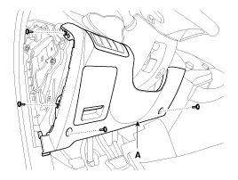
| 3. |
Loosen the mounting screw and then remove the crash pad lower cover (A).
|
| 4. |
Disconnect the connector (A), and then remove the crash pad lower cover.
|
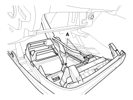
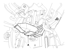
| 5. |
Remove the shower duct (A).
|
| 6. |
Loosen the mounting bolts and than remove the BCM.
(Refer to BE group - “BCM”) |
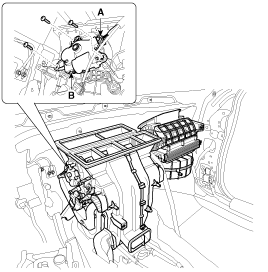
| 7. |
Disconnect the mode control actuator connector (A). |
| 8. |
Loosen the mounting screw and then remove the mode control actuator (B).
|
| 9. |
Installation is the reverse order of removal. |
 Mode Control Actuator Description and Operation
Description The mode control actuator is located at the heater unit. It adjusts position of mode door by operating mode control actuator based on signal of A/C control unit. Pressing mode select switch ...
 Heater hose pump Repair procedures
Inspection 1. Connect the battery voltage and check the heater hose pump motor rotation. 1. +2. - 2. If the heater hose pump voltage is not operated well, substitute with a known-good heater hose pump ...
Other information:
Kia Optima Hybrid (TF HEV) 2016-2020 Service Manual: Components and Components Location
Component Location Index Engine Room 1. Receiver Drier2. Condenser3. Service Port (High)4. Service Port (Low)5. A/C Pressure Transducer6. Compressor7. Expansion Valve Interior ...
Kia Optima Hybrid (TF HEV) 2016-2020 Service Manual: Radiator Components and Components Location
Components 1. Cooling fan assembly2. Radiator assembly3. Mounting insulator4. Radiator mounting bracket5. Radiator upper hose6. Radiator lower hose7. Reservoir tank8. Over flow hose ...