Kia Optima Hybrid: Engine Control System / Knock Sensor (KS) Repair procedures
Kia Optima Hybrid (TF HEV) 2016-2020 Service Manual / Engine Control/Fuel System / Engine Control System / Knock Sensor (KS) Repair procedures
| Removal |
| 1. |
Turn the ignition switch OFF and disconnect the battery negative (-) terminal. |
| 2. |
Drain the engine coolant (Refer to “Cooling System” in EM group). |
| 3. |
Remove the radiator upper hose (Refer to “Cooling System” in EM group). |
| 4. |
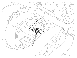
Disconnect the knock sensor connector (A).
|
| 5. |
Remove the intake manifold (Refer to “Intake And Exhaust System” in EM group). |
| 6. |
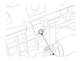
Remove the mounting bolt (A), and then remove the sensor from the cylinder block.
|
| Installation |
|
| 1. |
Install in the reverse order of removal.
|
 Knock Sensor (KS) Schematic Diagrams
Circuit Diagram ...
 Heated Oxygen Sensor (HO2S) Description and Operation
Description Heated Oxygen Sensor (HO2S) consists of zirconium and alumina and is installed both upstream and downstream of the Catalytic Converter. It varies in accordance with the air/fuel ratio. The ...
Other information:
Kia Optima Hybrid (TF HEV) 2016-2020 Service Manual: CVVT & Camshaft Components and Components Location
Components 1. Camshaft bearing cap2. Camshaft front bearing cap3. Exhaust camshaft4. Intake camshaft5. Exhaust CVVT assembly6. Intake CVVT assembly7. Exhaust camshaft upper bearing8. Intake camshaft lower bearing ...
Kia Optima Hybrid (TF HEV) 2016-2020 Service Manual: Body Control Module (BCM) Specifications
Specifications ItemsSpecificationsRated voltageDC 12VOperating voltageDC 9 ~ 16VOperating temperature-22°F~176°F(-30°C~ 80°C)Dark currentBCM & Receiver : 5.5mABCM : 4mA ...
© 2025 Copyright www.koptimatfhev.com


