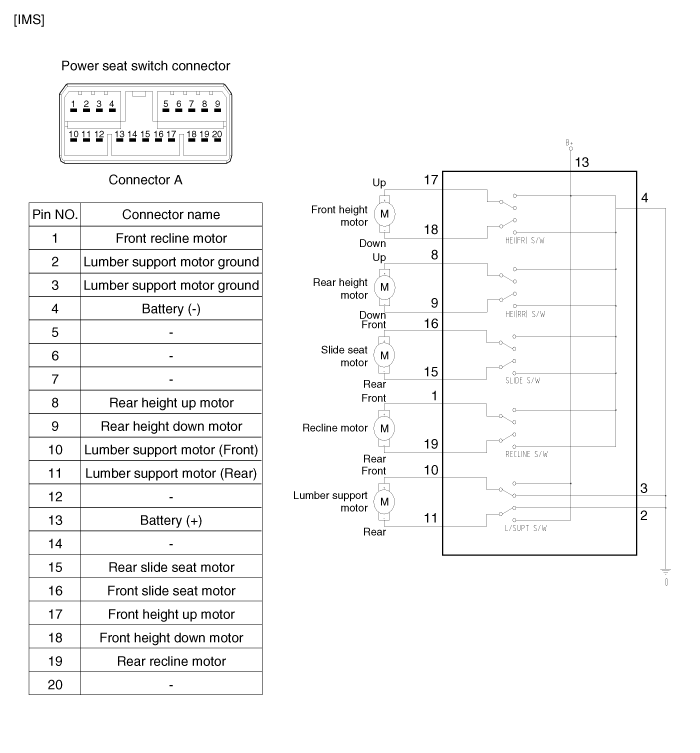
Kia Optima Hybrid: IMS (Integrated Memory) / IMS Control Switch Schematic Diagrams
| Circuit diagram |

 IMS Power Seat Control Repair procedures
Inspection 1. Disconnect the IMS control switch connector. 2. With the power IMS control switch in each position, make sure that continuity exists between the terminals below. If continuity is not as specified, ...
 IMS Control Switch Repair procedures
Inspection 1. Remove the IMS control switch connector (A). 2. With the IMS control switch in each position, make sure that continuity exists between the terminals below. If continuity is not as specified, ...
Other information:
Kia Optima Hybrid (TF HEV) 2016-2020 Service Manual: Intake Actuator Repair procedures
Inspection 1. Ignition "OFF". 2. Disconnect the intake actuator connector. 3. Verify that the actuator operates to the recirculation position when connecting 12V to the terminal 3 and grounding terminal 7. 4. Verify that the intake actuator operates to the fresh position when connecting in the reverse. ...
Kia Optima Hybrid (TF HEV) 2016-2020 Service Manual: Troubleshooting
Troubleshooting SymptomSuspect AreaRemedy (Refer to page)Water leaks from sunroofDeteriorated roof lid weatherstripReplaceExcessive roof lid-to-body clearance and improperly fitted weatherstripAdjustWind noise around sunroofLoose or deformed deflector, gaps in body workRe-tighten adjust or replaceNoise ...
