Kia Optima Hybrid: IMS (Integrated Memory) / IMS Control Switch Repair procedures
Kia Optima Hybrid (TF HEV) 2016-2020 Service Manual / Body Electrical System / IMS (Integrated Memory) / IMS Control Switch Repair procedures
| Inspection |
| 1. |
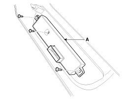
Remove the IMS control switch connector (A).
|
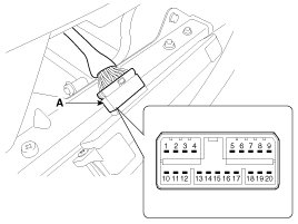
| 2. |
With the IMS control switch in each position, make sure that
continuity exists between the terminals below. If continuity is not as
specified, replace the IMS control switch.
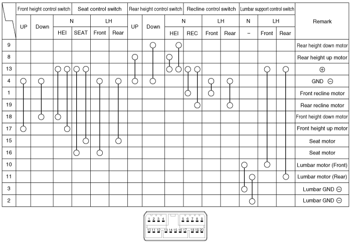
Driver Power Seat Control Switch (For IMS)
|
| Removal |
| 1. |
Disconnect the negative (-) battery terminal. |
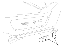
| 2. |
Remove the seat side cover switch (A).
|
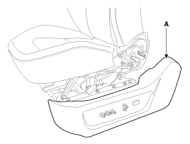
| 3. |
Remove the seat side cover (A).
(Refer to the BD group - "Front seat")
|
| 4. |
Disconnect the IMS control switch connector (A).
|
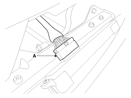
| 5. |
Loosen the IMS control switch (A) mounting screws (3EA).
|
| Installation |
|

| 1. |
Connect the connectors and reassemble the IMS control switch. |
| 2. |
Reassemble the seat side cover. |
 IMS Control Switch Schematic Diagrams
Circuit diagram ...
 Seat Electrical
...
Other information:
Kia Optima Hybrid (TF HEV) 2016-2020 Service Manual: License Lamp Repair procedures
Removal 1. Disconnect the negative(-) battery terminal. 2. Remove the license lamp (A) after pushing the pins fixed on the both side of license lamp. 3. Remove the bulb (B) by turning it counterclockwise. Installation 1. Install the bulb. 2. Install the license lamp assembly. ...
Kia Optima Hybrid (TF HEV) 2016-2020 Service Manual: Fender Repair procedures
Replacement • Be careful not to damage the fender and body. • When removing the clips, use a clip remover. 1. Remove the front bumper. (Refer to the BD group - "Front Bumper") 2. Loosen the mud guard mounting screws. 3. After loosening the mounting screws and clips, then remove the ...
© 2025 Copyright www.koptimatfhev.com