Kia Optima Hybrid: Automatic Transaxle System / Automatic Transaxle Repair procedures
| Removal |
|
| 1. |
Shut off the high voltage circuit.
( Refer to Automatic Transaxle System - "High Voltage Shut-off Procedure") |
| 2. |
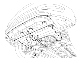
Remove the under cover (A).
|
| 3. |
Drain the coolant of hybrid motor cooling system.
( Refer to Hybrid Motor System - "Coolant") |
| 4. |
Drain the coolant of engine & transaxle cooling system.
(Refer to Engine Mechanical System - "Coolant ") |
| 5. |
Remove the hybrid power control unit assembly.
( Refer to Hybrid Control System - "HPCU (Hybrid Power Control Unit)" |
| 6. |
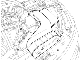
Remove the duct (A).
|
| 7. |
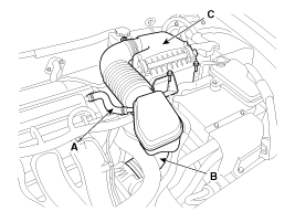
Remove the air cleaner assembly.
|
| 8. |
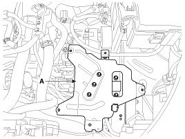
Remove the hybrid power control unit (HPCU) tray (A).
|
| 9. |
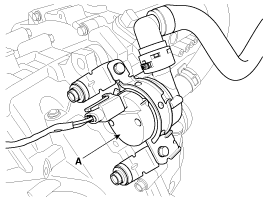
Remove heater hose pump (A).
|
| 10. |
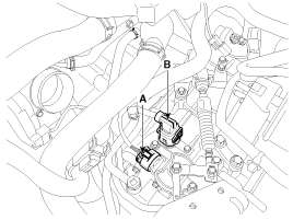
Disconnect the solenoid valve connector (B) and inhibitor switch connector (A).
|
| 11. |
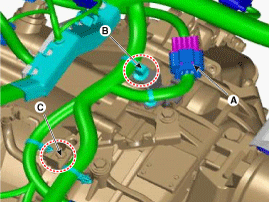
Disconnect the resolver sensor connector (A) and then remove the wiring bracket (B, C).
|
| 12. |
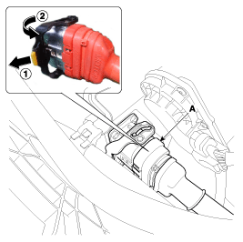
Remove the motor connector (A).
|
| 13. |
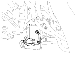
Remove the electric oil pump (EOP) connector (A).
|
| 14. |
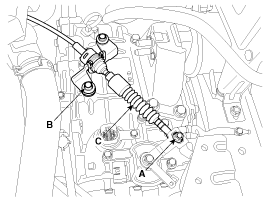
Remove the shift cable (C) after removing the nut (A) and the bolt (B).
|
| 15. |
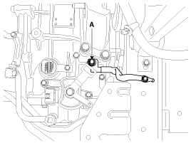
Remove the ground line after removing the bolt (A).
|
| 16. |
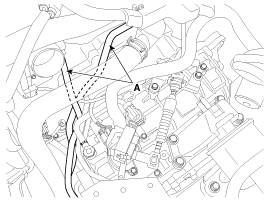
Remove the ATF warmer hose (A).
|
| 17. |
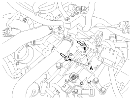
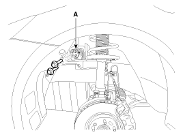
Remove the automatic transaxle upper mounting bolt (A-2ea).
|
| 18. |
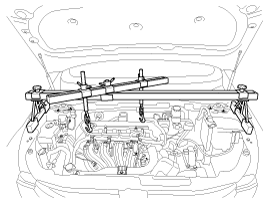
Assemble the engine support fixture.
(Refer to Special Service Tools-"Engine support fixture special tool assembly drawing") |
| 19. |
Using the engine support fixture, hold the engine and transaxle assembly safely.
|
| 20. |
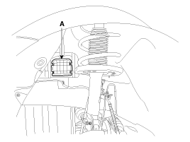
Remove the cover (A).
|
| 21. |
Remove the automatic transaxle mounting bracket bolts (A).
|
| 22. |
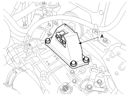
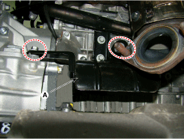
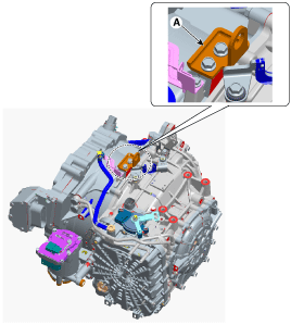
Remove the automatic transaxle support bracket (A).
|
| 23. |
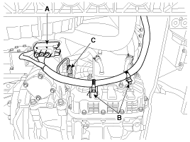
Remove the electric oil pump (EOP) connector (A) and clips (B). |
| 24. |
Remove the clutch pressure sensor (CPS) connector (C).
|
| 25. |
Remove the Drive shaft assembly.
(Refer to Driveshaft and axle - "Driveshaft Assembly") |
| 26. |
Remove the Sub frame assembly.
(Refer to Suspension System - "Front Suspension System") |
| 27. |
Remove the heat protector (A).
|
| 28. |
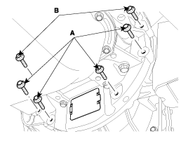
Remove the mounting bolts (A, B) after supporting the transaxle by a jack.
|
| 29. |
Remove the transaxle while slowly lower the jack.
|
| Installation |
| 1. |
Install in the reverse order of removal.
|
 Automatic Transaxle Components and Components Location
Components 1. Motor assembly2. Electric oil pump (EOP)3. Automatic transaxle case4. Rear cover5. Valve body cover6. Manual control lever7. Air breather hose8. Inhibitor switch9. Solenoid valve connector10. ...
 Hydraulic System
...
Other information:
Kia Optima Hybrid (TF HEV) 2016-2020 Service Manual: Description and Operation
Description System Overview The System offers the following features: – Human machine interface through a 1-stage button, for terminal switching and engine start. – Control of external relays for ACC / IGN1 / IGN2 terminal switching and STARTER, without use of mechanical ignition switch. – Indication ...
Kia Optima Hybrid (TF HEV) 2016-2020 Service Manual: Special Service Tools
Special Service Tools Tool(Number and Name)IllustrationUseDeployment tool0957A-34100AAirbag deployment tool.Deployment adapter0957A-3Q100Use with deployment tool.(DAB, CAB, BPT, APT)Deployment adapter0957A-2E110Use with deployment tool.(PAB)Deployment adapter0957A-3F100Use with deployment tool.(SAB)Dummy0957A-38200Simulator ...


