Kia Optima Hybrid: Hands Free System / Hands Free Switch Repair procedures
| Inspection |
| 1. |
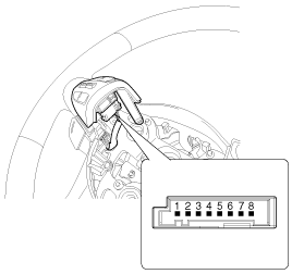
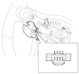
Check the hands free remote control switch for resistance between terminals in each switch position.
[Audio/ Bluetooth]
[Voice recognition]
[Bluetooth]
[Voice recognition]
|
| Removal |
| 1. |
Disconnect the negative (-) battery terminal. |
| 2. |
Remove the driver airbag module.
(Refer to the RT group) |
| 3. |
Remove the steering wheel.
(Refer to the ST group - "Steering column & shaft") |
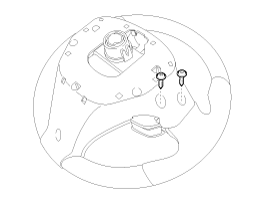
| 4. |
Loosen the mounting screws from the rear steering wheel cover.
|
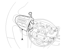
| 5. |
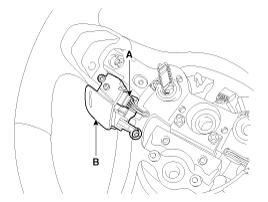
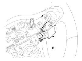
Separate the upper left steering wheel remote control switch (A) after loosening the mounting screw.
|
| 6. |
Remove the upper left steering wheel remote control switch (A) after disconnecting the connector.
|
| 1. |
Disconnect the negative (-) battery terminal. |
| 2. |
Remove the driver airbag module.
(Refer to the RT group) |
| 3. |
Remove the steering wheel.
(Refer to the ST group - "Steering column & shaft") |
| 4. |
Loosen the mounting screws from the front steering wheel cover. |
| 5. |
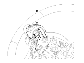
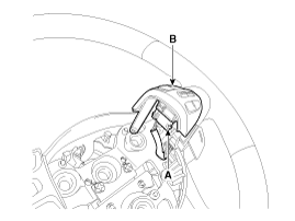
Remover the upper left steering wheel cover (A) after loosening the mounting screws. |
| 6. |
Remove the upper steering wheel remote control switch (A) after disconnecting the connector.
[LH]
[RH]
|
| 7. |
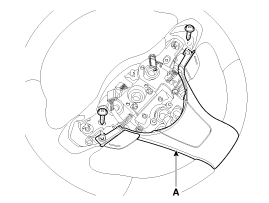
Remove the steering wheel cover (A) after loosening the mounting screws from the front steering wheel cover
|
| 8. |
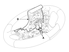
Remove the front steering wheel cover (B) after disconnecting the connector (A).
|
| 9. |
Remove the lower steering wheel remote control switch (B) after disconnecting the connector (A).
|
 Hands Free Switch Schematic Diagrams
Circuit Diagram ...
 Hands Free Mic Repair procedures
Inspection 1. Disconnect the negative(-) battery terminal. 2. Remove the roof trim. (Refer to the BD group - "Roof trim") 3. Remove the handsfree mic (A) after disconnect the connector from loof top. ...
Other information:
Kia Optima Hybrid (TF HEV) 2016-2020 Service Manual: Blower Unit Repair procedures
Replacement 1. Disconnect the negative (-) battery terminal. 2. Remove the crash pad and heater blower unit. (Refer to HA group-heater unit) 3. Remove the heater blower unit from crash pad. (Refer to HA group - "Heater Unit") 4. Remove the blower unit (A) from the heater unit after loosening a mounting ...
Kia Optima Hybrid (TF HEV) 2016-2020 Service Manual: Front Fog Lamps Repair procedures
Inspection 1. Disconnect the negative(-) battery terminal. 2. Remove the lighting switch of the multi-function switch. (Refer to the multi-function switch) 3. With the front fog lamp switch, make sure that continuity exists between the terminals below. If continuity is not as specified, replace the multi-function ...

