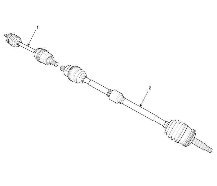
Kia Optima Hybrid: Driveshaft Assembly / Front Driveshaft Components and Components Location
| Component location |

| 1. Driveshaft (LH) | 2. Driveshaft (RH) |
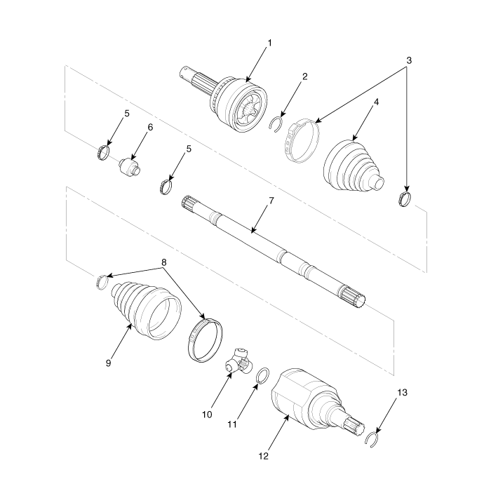
| Components |

| 1. BJ assembly 2. Circlip 3. BJ boot band 4. BJ boot | 5. Dynamic damper band 6. Dynamic damper 7. Shaft 8. TJ boot band | 9. TJ boot 10. Spider assembly 11. Snap ring 12. TJ case | 13. Circlip |
 Front Driveshaft Repair procedures
Replacement 1. Loosen the wheel nuts slightly. Raise the vehicle, and make sure it is securely supported. 2. Remove wheel nuts, front wheel and tire from front hub. Tightening torque: 88.2 ~ 107.8 N.m ...
Other information:
Kia Optima Hybrid (TF HEV) 2016-2020 Service Manual: Repair procedures
Inspection Test the horn by connecting battery voltage to the 1 terminal and ground the 2 terminal. The horn should make a sound. If the horn fails to make a sound, replace it. Horn Relay Inspection 1. Remove the horn relay (A) from the engine room relay box. 2. There should be continuity between the ...
Kia Optima Hybrid (TF HEV) 2016-2020 Service Manual: Hands Free Mic Repair procedures
Inspection 1. Disconnect the negative(-) battery terminal. 2. Remove the roof trim. (Refer to the BD group - "Roof trim") 3. Remove the handsfree mic (A) after disconnect the connector from loof top. Be careful not to damage the roof trim when removing the hands free mic. Do not reuse the ...

