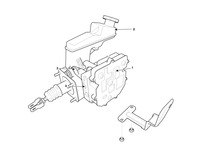
Kia Optima Hybrid: AHB(Active Hydraulic Boost) System / Brake Actuation Unit Components and Components Location
| Components |

IBAU must not be disassembled. |
| 1. ECU 2. Reservoir | 3. Master cylinder Assembley 4. Valve block |
 Description and Operation
Description Regeneration Brake System During deceleration or braking of an electric vehicle or HEV, the drive motor acts as an alternator and charges the battery by converting the vehicle’s kinetic energy ...
 Brake Actuation Unit Repair procedures
Removal 1. Turn ignition switch OFF and disconnect the negative (-) battery cable. 2. Remove the air duct (A). 3. Remove air cleaner assembly (B). 4. Disconnect the brake fluid level switch connector (A), ...
Other information:
Kia Optima Hybrid (TF HEV) 2016-2020 Service Manual: Auto Light Sensor Repair procedures
Inspection In the state of IGN1 ON, when multi function switch module detects auto light switch on, tail lamp relay output and head lamp low relay output are controlled according to auto light sensor''s input. The auto light control doesn''t work if the pin sunlight supply (5V regulated power from Ignition ...
Kia Optima Hybrid (TF HEV) 2016-2020 Service Manual: Valve Clearance Adjustment
Valve Clearance Inspection And Adjustment Inspect and adjust the valve clearance when the engine is cold (Engine coolant temperature : 20°C (68°F)) and cylinder head is installed on the cylinder block. 1. Remove the cylinder head cover. (Refer to Timing system in this group) 2. Set No.1 ...

