Kia Optima Hybrid: AHB(Active Hydraulic Boost) System / Brake Actuation Unit Repair procedures
| Removal |
| 1. |
Turn ignition switch OFF and disconnect the negative (-) battery cable. |
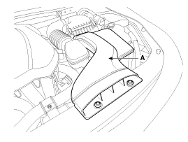
| 2. |
Remove the air duct (A).
|
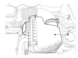
| 3. |
Remove air cleaner assembly (B).
|
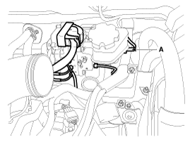
| 4. |
Disconnect the brake fluid level switch connector (A), and remove the reservoir cap.
|

| 5. |
Remove the brake fluid from the reservoir with a syringe.
|
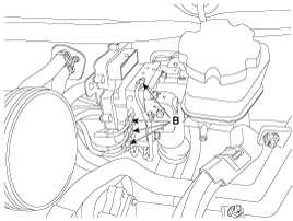
| 6. |
Disconnect reservoir hose from the reservoir and IBAU connecter (A).
|
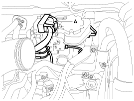
| 7. |
Disconnect the brake tube from the IBAU by loosening the tube flare nut (B).
|

| 8. |
Remove the brake pedal assembly. (Refer to the brake system group - brake pedal) |
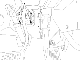
| 9. |
Remove the IBAU mounting nuts (A) and then remove the IBAU.
|
| Installation |
| 1. |
Installation is the reverse of removal. |
| 2. |
Check the brake pedal operation. |
| 3. |
After filling the brake fluid in the reservoir, perform the air bleed. (Refer to the Brakde system - Brake Bleeding Procedures) |
| 4. |
Conduct calibration after removing the brake pedal assembly. (Refer to the brake pedal - calibration) |
 Brake Actuation Unit Components and Components Location
Components IBAU must not be disassembled. 1. ECU2. Reservoir3. Master cylinder Assembley 4. Valve block ...
 Pressure Source Unit Components and Components Location
Components PSU must not be disassembled. 1. Motor connecter2. Bracket3. Block4. Accumulator5. Damper6. Motor ...
Other information:
Kia Optima Hybrid (TF HEV) 2016-2020 Service Manual: Blind Spot Detection Unit Repair procedures
Removal Blind spot detection (BSD) unit 1. Disconnect the negative (-) battery. Be careful when removing the blind spot detection unit. The bracket may break off from the bumper. 2. Remove the rear bumper. (Refer to Body - "Rear Bumper Cover") 3. Disconnect the BSD connector (A) from the ...
Kia Optima Hybrid (TF HEV) 2016-2020 Service Manual: Fuel Line Repair procedures
Removal 1. Remove the fuel tank (Refer to “Fuel Tank”) 2. Disconnect the fuel feed tube (A). 3. Disconnect the vapor hose (A). 4. Disconnect the vapor hose quick-connector (A). 5. Remove the fuel tube protector (A). 6. Unfasten the fuel tube holders (B). 7. Make a gap for removing the fuel line by ...