Kia Optima Hybrid: Hydraulic System / Valve Body Components and Components Location
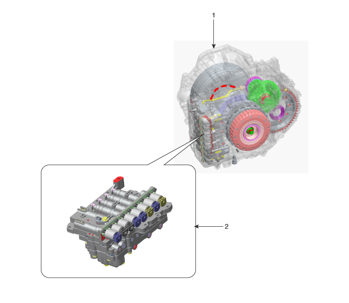
| Component Location |

| 1. Automatic transaxle | 2. Valve body assembly |
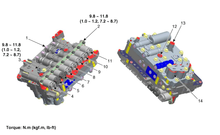
| Component |

| 1. Pressure Control Valve(PCV) adjust screw | 8. Underdrive Brake Control Solenoid Valve(UD/B) |
| 2. Solenoid valve bracket | 9. 26 Brake Control Solenoid Valve(26/B) |
| 3. Oil temperature sensor | 10. 35R Clutch Control Solenoid Valve(35R/C) |
| 4. Line Pressure Control Solenoid Valve | 11. Torque Converter Control Solenoid Valve (T/CON) |
| 5. SS-A Solenoid Valve(ON/OFF) | 12. LR/B pressure flow hole |
| 6. SS-B Solenoid Valve(ON/OFF) | 13. UD/B pressure flow hole |
| 7. Overdrive Clutch Control Solenoid Valve(OD/C) | 14. Accumulator |
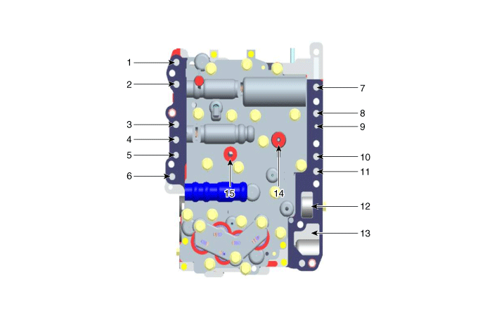
| Valve Body Flow |

| 1. To cooler | 9. Lubrication (Front) |
| 2. From cooler | 10. 35R clutch pressure |
| 3. Lubrication (Rear) | 11. 26 brake pressure |
| 4. Overdrive pressure | 12. From oil pump |
| 5. Reducing pressure (red2) | 13. To oil pump |
| 6. Reducing pressure (red1) | 14. Underdrive pressure |
| 7. Engine clutch pressure | 15. Low & reverse pressure |
| 8. Lubrication (Engine clutch) | ? |
 Valve Body Description and Operation
Description The valve body is essential to automatic transaxle control and consists of various valves used to control the oil feed from the oil pump. Specifically, these valves consist of pressure regulator ...
 Valve Body Repair procedures
Removal • Be sure to read and follow the “General Safety Information and Caution” before doing any work related with the high voltage system. Failure to follow the safety instructions ...
Other information:
Kia Optima Hybrid (TF HEV) 2016-2020 Service Manual: Compass Mirror Repair procedures
Calibration Procedure If the compass has been calibrated or set to variance zone number incorrectly, or you are driving in specific places (tunnel, parking lot in building, underground parking lot, near transformer substation, etc.), the below conditions may occur. • The display read "C". • The compass ...
Kia Optima Hybrid (TF HEV) 2016-2020 Service Manual: Air Ventilation Seat Components and Components Location
Components (1) 1. Ventilation blower2. Ventilation ECU3. Ventilation seat switch Components (2) Components (3) ...
