Kia Optima Hybrid: Automatic Transaxle Control System / Transaxle Control Module (TCM) Repair procedures
| Inspection |
| TCM Problem Inspection Procedure |
| 1. |
TEST TCM GROUND CIRCUIT: Measure resistance between TCM and
chassis ground using the backside of TCM harness connector as TCM side
check point. If the problem is found, repair it.
|
| 2. |
Test TCM Connector: Disconnect the TCM connector and visually
check the ground terminals on TCM side and harness side for bent pins
or poor contact pressure. If the problem is found, repair it. |
| 3. |
If problem is not found in Step 1 and 2, the TCM could be
faulty. If so, make sure there were no DTC''s before swapping the TCM
with a new one, and then check the vehicle again. If DTC''s were found,
examine this first before swapping TCM. |
| 4. |
Re - test the Original TCM : Install the original TCM (may be
broken) into a known-good vehicle and check the vehicle. If the problem
occurs again, replace the original TCM with a new one. If problem does
not occur, this is intermittent problem. |
| Removal |
|
| 1. |
Disconnect the 12V battery negative (-) cable. |
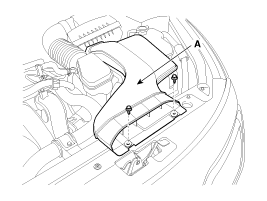
| 2. |
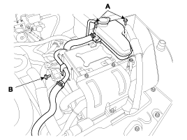
Remove the air duct (A).
|
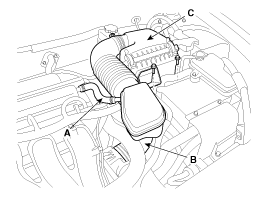
| 3. |
Remove the air cleaner assembly.
|
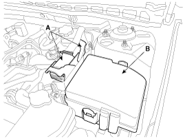
| 4. |
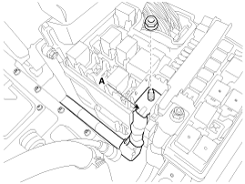
Disconnect the TCM connector (A) and remove the room relay box cover (B).
|
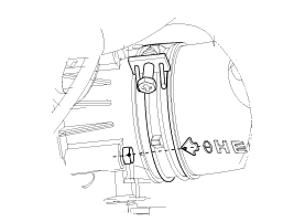
| 5. |
Remove the resolver mounting bolt (A) and drain pipe fixed bolt (B) and then spaced the HPCU.
|
| 6. |
Remove the battery (+) cable (A) after removing nut.
|
| 7. |
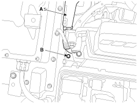
Push back the battery (+) cable (A) and then remove the TCM bracket mounting bolt (B).
|
| 8. |
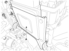
Remove the TCM (A) after removing TCM bracket mounting nut.
|
| Installation |
| 1. |
Install in the reverse order of removal.
|
 Transaxle Control Module (TCM) Schematic Diagrams
TCM connector and terminal function TCM terminal function Connector [A] PinDescriptionPinDescription2-33ON/OFF solenoid valve A (SS-A)3Line pressure control solenoid valve (LINE_VFS)34Ground (Power 1)4Engine ...
 Transaxle Oil Temperature Sensor Description and Operation
Description Transaxle oil temperature sensor monitors the automatic transaxle fluid''s temperature and conveys the readings to TCM. It is an NTC (Negative Thermal Coefficient) sensor whose resistance has ...
Other information:
Kia Optima Hybrid (TF HEV) 2016-2020 Service Manual: AVN Head Unit Components and Components Location
Components AVN (A/V & Navigation) Head Unit Connector Connecotr Pin Information No.Connector A (18pin)Connector B (24pin)Connector C (24pin)1-MM CAN highC CAN (-)2--C CAN (+)3---4-Steering remote control-5SPDIF ground--6SPDIF (+)MTS key-7-AUX video-8Illumination (+)AUX right input-9ReverseAUX ground-10-MIC ...
Kia Optima Hybrid (TF HEV) 2016-2020 Service Manual: Description and Operation
Description Tread Lamp – Tire Under Inflation / Leak Warning. 1. Turn on condition • When tire pressure is below allowed threshold • When rapid leak is detected by the sensor. 2. Turn off condition • When tire pressure is above(warning threshold + hysteresis). • When tire pressure is above ...


