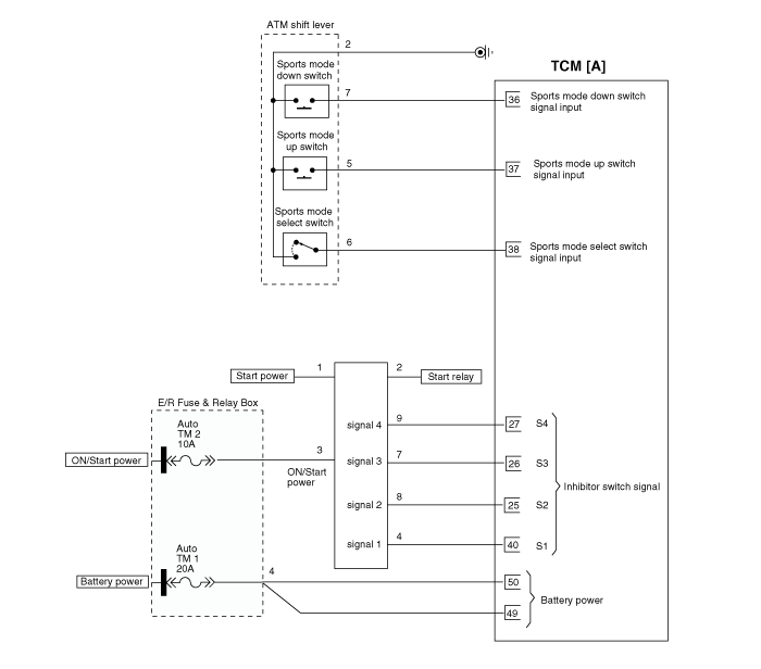
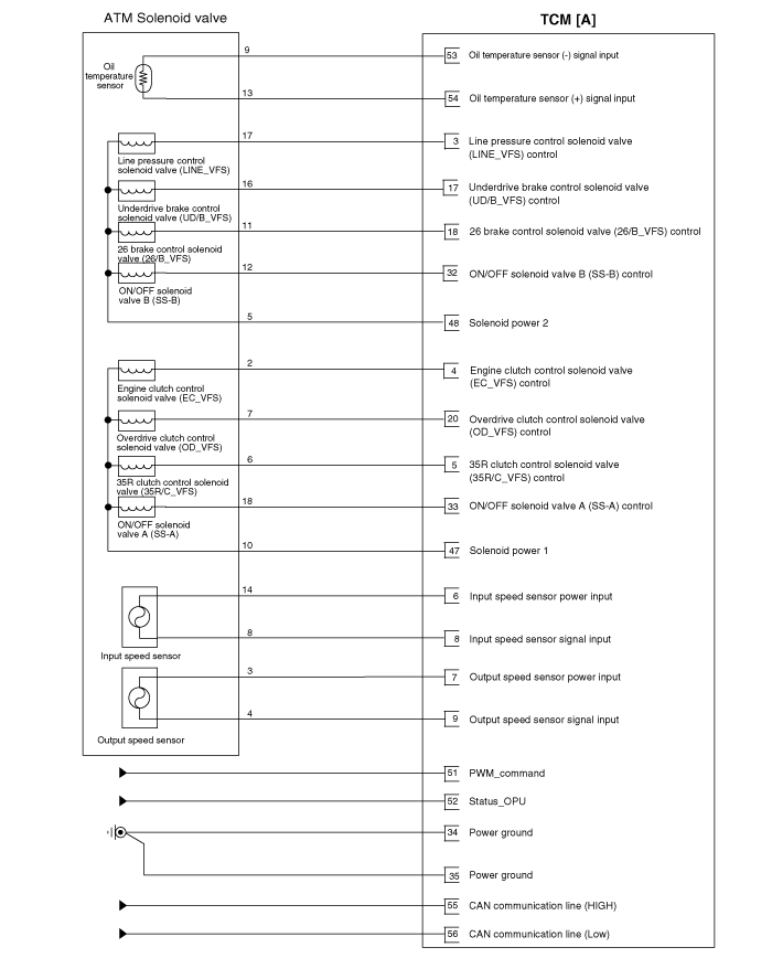
Kia Optima Hybrid: Automatic Transaxle Control System / Transaxle Control Module (TCM) Schematic Diagrams
| TCM connector and terminal function |

| TCM terminal function |
| Pin | Description | Pin | Description |
| 2 | - | 33 | ON/OFF solenoid valve A (SS-A) |
| 3 | Line pressure control solenoid valve (LINE_VFS) | 34 | Ground (Power 1) |
| 4 | Engine clutch control solenoid valve (EC_VFS) | 35 | Ground (Power 2) |
| 5 | 35R clutch control solenoid valve (35R/C_VFS) | 36 | Sports mode down switch |
| 6 | Input speed sensor power | 37 | Sports mode up switch |
| 7 | Output speed sensor power | 38 | Sports mode select switch |
| 8 | Input speed sensor signal | 40 | Inhibitor switch signal "S1" |
| 9 | Output speed sensor signal | 47 | Solenoid supply power 1 |
| 17 | Underdrive brake control solenoid valve (UD/B_VFS) | 48 | Solenoid supply power 2 |
| 49 | TCM Input power 1 (For solenoid) | ||
| 18 | 26 brake control solenoid valve (26/B_VFS) | 50 | TCM Input power 2 (For solenoid) |
| 19 | Shift lock solenoid | 51 | PWM_command |
| 20 | Overdrive clutch control solenoid valve (OD/C_VFS) | 52 | Status_OPU |
| 53 | Oil temperature sensor (-) | ||
| 25 | Inhibitor switch signal "S2" | 54 | Oil temperature sensor (+) |
| 26 | Inhibitor switch signal "S3" | 55 | CAN communication line (HIGH) |
| 27 | Inhibitor switch signal "S4" | 56 | CAN communication line (Low) |
| 32 | ON/OFF solenoid valve B (SS-B) | 56 | CAN communication line (Low) |
| 33 | ON/OFF solenoid valve A (SS-A) | ? | ? |
| Pin | Description | Pin | Description |
| 1 | Power ground | 4 | Battery power (B+) |
| 2 | Battery power (B+) | 5 | ECU ground |
| 3 | Power ground | 6 | Battery power (B+) |
| Pin | Description | Condition | Input/output value | |
| Type | Level | |||
| 3 | Line pressure control solenoid valve (LINE_VFS) | ? | Output | 0V/Battery voltage level 9V < Battery voltage level < 16V |
| 4 | Engine clutch control solenoid valve (EC_VFS) | ? | Output | 0V/Battery voltage level 9V < Battery voltage level < 16V |
| 5 | 35R clutch control solenoid valve (35R/C_VFS) | ? | Output | 0V/Battery voltage level 9V < Battery voltage level < 16V |
| 6 | Input speed sensor power | ON | Power | 0V/7.5V |
| OFF | ||||
| 7 | Output speed sensor power | ON | Power | 0V/7.5V |
| OFF | ||||
| 8 | Input speed sensor signal | High | Input | 0.7V/1.4V |
| Low | ||||
| 9 | Output speed sensor signal | High | Input | 0.7V/1.4V |
| Low | ||||
| 17 | Underdrive brake control solenoid valve (UD/B_VFS) | ? | Output | 0V/Battery voltage level 9V < Battery voltage level < 16V Power supply : V_SOL2 |
| 18 | 26 brake control solenoid valve (26/B_VFS) | ? | Output | 0V/Battery voltage level 9V < Battery voltage level < 16V Power supply : V_SOL2 |
| 19 | Shift lock solenoid | High | Output | 0V/Battery voltage level9V < Battery voltage level < 16V |
| Low | ||||
| 20 | Overdrive clutch control solenoid valve (OD/C_VFS) | ? | Output | 0V/Battery voltage level 9V < Battery voltage level < 16V Power supply : V_SOL1 |
| 22 | Rear lamp relay | R ON | Output | 0V/Battery voltage level 9V < Battery voltage level < 16 |
| Other | ||||
| 25 | Inhibitor switch signal "S2" | High | Input | 0V/Battery voltage level 9V < Battery voltage level < 16V |
| Low | ||||
| 26 | Inhibitor switch signal "S3" | High | Input | 0V/Battery voltage level 9V < Battery voltage level < 16V |
| Low | ||||
| 27 | Inhibitor switch signal "S4" | High | Input | 0V/Battery voltage level 9V < Battery voltage level < 16V |
| Low | ||||
| 32 | ON/OFF solenoid valve B(SS-B) | High | Output | 0V / Battery voltage level 9V < Battery voltage level < 16V |
| Low | ||||
| 33 | ON/OFF solenoid valve A (SS-A) | High | Output | 0V / Battery voltage level 9V < Battery voltage level < 16V |
| Low | ||||
| 34 | Ground (Power 1) | ? ? | Ground | 0V |
| 35 | Ground (Power 2) | Ground | 0V | |
| 36 | Sports mode down switch | Down ON | Input | 0V/Battery voltage level 9V < Battery voltage level < 16V |
| Other | ||||
| 37 | Sports mode up switch | Up ON | Input | 0V/Battery voltage level 9V < Battery voltage level < 16V |
| Other | ||||
| 38 | Sports mode select switch | Sport mode | Input | 0V/Battery voltage level 9V < Battery voltage level < 16V |
| Other | ||||
| 40 | Inhibitor switch signal "S1" | High | Input | 0V/Battery voltage level 9V < Battery voltage level < 16 |
| Low | ||||
| 47 | Solenoid supply power 1 | ON | Power | 0V/Battery voltage level 9V < Battery voltage level < 16V |
| OFF | ||||
| 48 | Solenoid supply power 2 | ON | Power | 0V/Battery voltage level 9V < Battery voltage level < 16V |
| OFF | ||||
| 49 | TCM Input power 1 (For solenoid) | ? | Power | Battery voltage level 9V < Battery voltage level < 16V |
| 50 | TCM Input power 2 (For solenoid) | ? | Power | Battery voltage level 9V < Battery voltage level < 16 |
| 51 | PWM_command | ? ? | Output | 0V / Battery voltage level 9V < Battery voltage level < 16V |
| 52 | Status_OPU | Input | 0V / Battery voltage level 9V < Battery voltage level < 16V | |
| 53 | Oil temperature sensor (-) | ? | Ground | 0V |
| 54 | Oil temperature sensor (+) | ON? | Input? | ?0V/3.3V |
| OFF | ||||
| 55 | CAN communication line (HIGH) | High? | Command? | ? |
| Low? | ||||
| 56 | CAN communication line (Low)? | High? | Command? | ? |
| Low? | ||||
| Circuit Diagram |


 Transaxle Control Module (TCM) Description and Operation
Description Transaxle Control Module (TCM) is the automatic transaxle''s brain. The module receives and processes signals from various sensors and implements a wide range of transaxle controls to ensure ...
 Transaxle Control Module (TCM) Repair procedures
Inspection TCM Problem Inspection Procedure 1. TEST TCM GROUND CIRCUIT: Measure resistance between TCM and chassis ground using the backside of TCM harness connector as TCM side check point. If the problem ...
Other information:
Kia Optima Hybrid (TF HEV) 2016-2020 Service Manual: Injector Repair procedures
Inspection 1. Turn the ignition switch OFF. 2. Disconnect the injector connector. 3. Measure resistance between the injector terminals 1 and 2. 4. Check that the resistance is within the specification. Specification: 13.8 ~ 15.2? [20°C(68°F)] Removal 1. Turn the ignition switch OFF and disconnect the ...
Kia Optima Hybrid (TF HEV) 2016-2020 Service Manual: Thermostat Troubleshooting
Troubleshooting SymptomsPossible CausesRemedyCoolant leakage • From the thermostat gasket Check the mounting bolts • Check the torque of the mounting bolts • Retighten the bolts and check leakage again. Check the gasket for damage • Check gasket or seal for damage • Replace gaskets and reuse ...
