Kia Optima Hybrid: Tire Pressure Monitoring System / TPMS Receiver Description and Operation
| Description |
| 1. |
Initial state
|
| 2. |
Normal operation states
|
 TPMS Sensor Repair procedures
Removal Tire Removal 1. Deflate tire & remove balance weights. • The tire bead should be broken approx. 90° from the valve side of the wheel. The bead breaker should not be set too ...
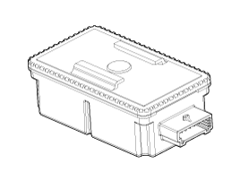
 TPMS Receiver Schematic Diagrams
Circuit Diagram Connector pin number Pin NO.DiscriptionRemark1-2-3ECU battery terminal4-5CAN_High6CAN_Low7-8-9Ground10-11-12-13-14-15-16-17-18Ignition ON19-20- ...
Other information:
Kia Optima Hybrid (TF HEV) 2016-2020 Service Manual: Rear Stabilizer Bar Repair procedures
Replacement 1. Remove the rear wheel & tire. Tightening torque: 88.3 ~ 107.9N.m (9.0 ~ 11.0kgf.m, 65.1 ~ 79.6lb-ft) Be careful not to damage the hub bolts when removing the rear wheel & tire. 2. Loosen the nut and then remove the rear stabilizer link (B) from the rear lower arm ...
Kia Optima Hybrid (TF HEV) 2016-2020 Service Manual: Seat Belt Pretensioner (BPT) Repair procedures
Removal 1. Disconnect the battery negative cable, and wait for at least three minutes before beginning work. 2. To remove the seat belt anchor pretensioner (C), keep on pushing the lock pin (A) as arrow direction. And then remove the seat belt after pushing the lock pin (B). 3. Remove the door scuff ...