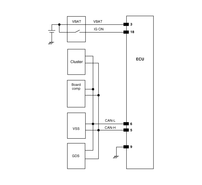
Kia Optima Hybrid: Tire Pressure Monitoring System / TPMS Receiver Schematic Diagrams
| Circuit Diagram |

| Connector pin number |

| Pin NO. | Discription | Remark |
| 1 | - | |
| 2 | - | |
| 3 | ECU battery terminal | |
| 4 | - | |
| 5 | CAN_High | |
| 6 | CAN_Low | |
| 7 | - | |
| 8 | - | |
| 9 | Ground | |
| 10 | - | |
| 11 | - | |
| 12 | - | |
| 13 | - | |
| 14 | - | |
| 15 | - | |
| 16 | - | |
| 17 | - | |
| 18 | Ignition ON | |
| 19 | - | |
| 20 | - |
 TPMS Receiver Description and Operation
Description It automatically searches the sensor location and learns new sensors. It uses the sensor information, distance travelled, indistinct noise, automatic learning status, vehicle battery condition ...
 TPMS Receiver Description and Operation
Operation 1. General Function • Auto-locate/learn takes place only once per Ignition cycle. • On successful completion, 4 road wheel sensor ID''s, together with their respective road wheel positions ...
Other information:
Kia Optima Hybrid (TF HEV) 2016-2020 Service Manual: Blind Spot Detection Variant Coding Description and Operation
Description The used radar frequency of BSD is two, "North America region" and "Except North America region". If it replaces BSD unit, BSD unit has to perform the procedure of variant coding. BSD Variant Coding 1. Select the "BSD Variant Coding" procedure in BSD system. 2. Perform the "BSD Variant Coding" ...
Kia Optima Hybrid (TF HEV) 2016-2020 Service Manual: Seat Heater Repair procedures
Inspection First Seat Heater 1. Check for continuity and measure the resistance between No.4 and No.6 terminals. [Cushion] No.DescriptionNo.Description1NTC4GND2-5GND3NTC6VCC [Back] Standard value (Fabric / Leather) Cushion : 3.89 ? ± 10% Back: 3.11 ? ± 10% / 4.13 ? ± 10% Set : 7.0 ? ± 10% / 8.9 ? ...
