Kia Optima Hybrid: Smart key System / Smart key unit Repair procedures
Kia Optima Hybrid (TF HEV) 2016-2020 Service Manual / Body Electrical System / Smart key System / Smart key unit Repair procedures
| Inspection |
Smart Key Unit
| – |
Refer to the BE group - inspection / self diagnosis with GDS. |
Smart Key Switch
| – |
Refer to the BE group - inspection / self diagnosis with GDS. |
Antenna
| – |
Refer to the BE group - inspection / self diagnosis with GDS. |
Trunk Lid Open Switch
| 1. |
Check for continuity between the Trunk lid open switch terminals.
|
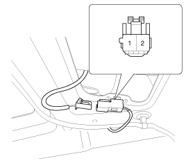
| 2. |
If continuity is not specified, inspect the switch
|
| Removal |
|

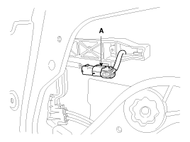
Smart key unit
| 1. |
Disconnect the negative(-) battery terminal. |
| 2. |
Remove the glove box.
(Refer to the BD group - "Crash pad") |
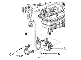
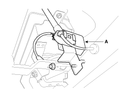
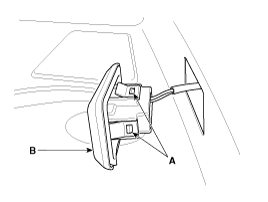
| 3. |
Remove the smart key unit (A) after disconnecting the connector and loosening the mounting nuts (2EA).
|
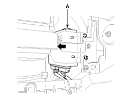
| 4. |
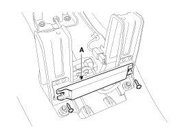
Remove the smart key unit (A) with bracket (B) after loosening the mounting nuts, shear bolts (C).
[CANADA]
|

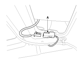
RF Receiver
|
| 1. |
Disconnect the negative(-) battery terminal. |
| 2. |
Remove the glove box.
(Refer to the BD group - "Crash pad") |
| 3. |
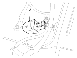
Remove the RF receiver (A) after loosening the mounting nuts (1EA) and disconnecting the connector.
|
Interior 1 Antenna
|
| 1. |
Disconnect the negative(-) battery terminal. |
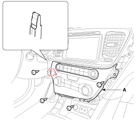
| 2. |
Remove the heater control unit (A) after removing the screws.
(Refer to the BD group - "Crash pad")
|
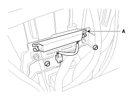
| 3. |
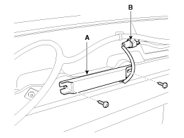
Remove the interior 1 antenna (A) after disconnecting the connector and loosening the mounting nuts (2EA).
|
Interior 2 Antenna
| 1. |
Disconnect the negative(-) battery terminal. |
| 2. |
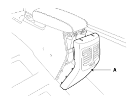
Remove the center console rear cover (A).
|
| 3. |
Disconnect the interior 2 antenna connector located at the
console rear side, then remove the interior 2 antenna (A) after
loosening screws (2EA).
|
Trunk Antenna
| 1. |
Disconnect the negative(-) battery terminal. |
| 2. |
Remove the trunk transverse trim.
(Refer to the BD group - "Interior trim") |
| 3. |
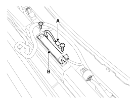
Disconnect the trunk antenna connector (A) and remove the trunk antenna (B) after loosening nut (2EA).
|
Exterior Bumper Antenna
| 1. |
Disconnect the negative(-) battery terminal. |
| 2. |
Remove the rear bumper.
(Refer to the BD group - "Rear bumper") |
| 3. |
Disconnect the antenna connector (B) and remove the exterior bumper antenna (A) after loosening the screws (2EA).
|
Buzzer
| 1. |
Disconnect the negative(-) battery terminal. |
| 2. |
Remove the left side wheel guard. |
| 3. |
Remove the external buzzer (A) after disconnecting the connector.
|
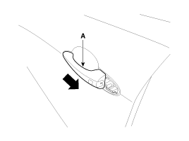
Door Outside Handle
| 1. |
Disconnect the negative (-) battery terminal. |
| 2. |
Remove the front door module.
(Refer to the BD group - "Front door") |
| 3. |
Remove the hole plug (B). |
| 4. |
After loosening the mounting bolt, then remove the outside handle cover (A).
|
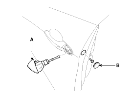
| 5. |
Remove the outside handle (A) by sliding it rearward.
|
| 6. |
Disconnect the outside handle connector (A).
|
Trunk lid open switch
| 1. |
Disconnect the negative(-) battery terminal. |
| 2. |
Remove the trunk door trim.
(Refer to the BD group - "Trunk") |
| 3. |
Disconnect the trunk lid open switch connector (A).
|
| 4. |
Remove the trunk open switch (A) from the trunk garnish after pressing the clips (B).
|
| Installation |
Smart Key Unit
| 1. |
Install the smart key unit. |
| 2. |
Install the smart key unit mounting nuts and bolts and connector. |
| 3. |
Install the glove box housing. |
| 4. |
Install the glove box. |
| 5. |
Install the negative (-) battery terminal and check the smart key system. |
RF Receiver
| 1. |
Install the RF receiver. |
| 2. |
Install the glove box housing. |
| 3. |
Install the glove box. |
| 4. |
Install the negative (-) battery terminal and check the smart key system. |
Interior 1 Antenna
| 1. |
Install the interior 1 antenna. |
| 2. |
Install the heater control unit |
| 3. |
Install the negative (-) battery terminal and check the smart key system. |
Interior 2 Antenna
| 1. |
Install the interior 2 antenna. |
| 2. |
Install the console rear cover after connecting the connector. |
| 3. |
Install the negative (-) battery terminal and check the smart key system. |
Trunk Antenna
| 1. |
Install the trunk antenna. |
| 2. |
Install the trunk trim. |
| 3. |
Install the negative (-) battery terminal and check the smart key system. |
Exterior Bumper Antenna
| 1. |
Install the exterior bumper antenna. |
| 2. |
Install the rear bumper. |
| 3. |
Install the negative (-) battery terminal and check the smart key system. |
Buzzer
| 1. |
Install the buzzer. |
| 2. |
Install the left side wheel guard. |
| 3. |
Install the negative (-) battery terminal and check the smart key system. |
Trunk Lid Open Switch
| 1. |
Install the trunk lid open switch. |
| 2. |
Install the trunk trim. |
| 3. |
Install the negative (-) battery terminal and check the smart key system. |
Door Outside Handle
| 1. |
Install the outside handle. |
| 2. |
Install the door trim. |
| 3. |
Install the negative (-) battery terminal and check the smart key system. |
 Smart key unit Schematic Diagrams
Circuit Diagram ...

Other information:
Kia Optima Hybrid (TF HEV) 2016-2020 Service Manual: Repair procedures
Removal 1. Disconnect the negative (-) battery terminal. 2. Remove the driver crash pad lower panel. (Refer to the BD group - "Crash pad") 3. Remove the steering column upper and lower shrouds. (Refer to the BD group - "Crash pad") 4. Remove the wiper switch. (Refer to the BE group - "Multifunction switch") ...
Kia Optima Hybrid (TF HEV) 2016-2020 Service Manual: Fluid Repair procedures
Inspection ATF level Check When checking the ATF level, be careful not to enter dust, foreign matters, etc. from fill hole. 1. Remove the air duct (A). 2. Remove the eyebolt (A). 3. Add ATF SP-IV 700cc to the ATF injection hole (A). 4. Start the engine. (Don’t step on brake and accelerator ...
© 2025 Copyright www.koptimatfhev.com