Kia Optima Hybrid: Ignition Switch Assembly / Repair procedures
Kia Optima Hybrid (TF HEV) 2016-2020 Service Manual / Body Electrical System / Ignition Switch Assembly / Repair procedures
| Removal |
| 1. |
Disconnect the negative (-) battery terminal. |
| 2. |
Remove the driver crash pad lower panel.
(Refer to the BD group - "Crash pad") |
| 3. |
Remove the steering column upper and lower shrouds.
(Refer to the BD group - "Crash pad") |
| 4. |
Remove the wiper switch.
(Refer to the BE group - "Multifunction switch") |
| 5. |
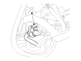
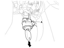
Remove the ignition switch after disconnecting the ignition switch 6P connector (A)
|
| 6. |
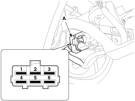
Remove the key warning/immobilizer connector (A).
|
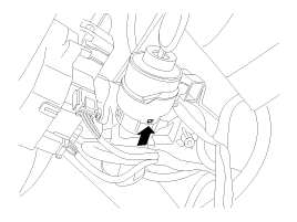
| 7. |
After loosening the screw, remove the key warning switch and key Illumination (A).
|
| 8. |
Pushing lock pin with key ACC.
|
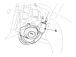
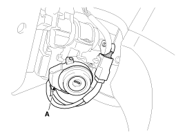
| 9. |
Remove the key lock cylinder (A).
|
| Installation |
| 1. |
Install the key lock cylinder. |
| 2. |
Install the key warning switch and key Illumination. |
| 3. |
Install the key warning/immobilizer connector. |
| 4. |
Connect the ignition switch connector after Install the ignition switch. |
| 5. |
Install the wiper switch. |
| 6. |
Install the steering column shrouds. |
| 7. |
Install the driver crash pad lower panel. |
| Inspection |
| 1. |
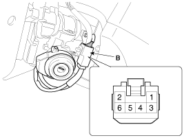
Disconnect the ignition switch connector (A) and key warning switch connector (B) from the steering column.
|
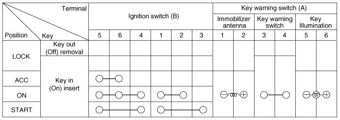
| 2. |
Check for continuity between the terminals. |
| 3. |
If continuity is not specified, replace the switch.
|


Other information:
Kia Optima Hybrid (TF HEV) 2016-2020 Service Manual: Rear combination lamp Repair procedures
Removal Rear Combination lamp (Outside) 1. Disconnect the negative (-) battery terminal. 2. Remove the rear combination lamp cover (A). 3. Replace the turn signal lamp bulbs (A) by turning it counterclockwise. 4. Disconnect the connector (A) and then loosen the mounting nuts. 5. Remove the rear combination ...
Kia Optima Hybrid (TF HEV) 2016-2020 Service Manual: Specifications
Specification Air Conditioner ItemSpecificationCompressorTypeESC33iOil type & CapacityPOE OIL 3.8~4.5oz. (115~135cc)Motor typeBLDCDisplacement33cc/revCondenserHeat rejection14,000 ± 5% kcal/hrA/C Pressure transducerThe method to measure the pressureVoltage = 0.00878835 * Pressure (psig) + 0.5Expansion ...
© 2025 Copyright www.koptimatfhev.com