Kia Optima Hybrid: Hydraulic System / Fluid Repair procedures
| Inspection |
| ATF level Check |
When checking the ATF level, be careful not to enter dust, foreign matters, etc. from fill hole. |

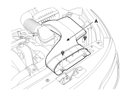
| 1. |
Remove the air duct (A).
|
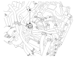
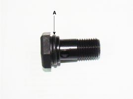
| 2. |
Remove the eyebolt (A). |
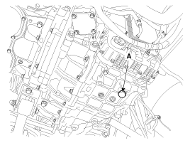
| 3. |
Add ATF SP-IV 700cc to the ATF injection hole (A).
|
| 4. |
Start the engine. (Don’t step on brake and accelerator simultaneously) |
| 5. |
Confirm that the temperature of the A/T oil temperature sensor is 50~60°C(122~140°F) with the GDS. |
| 6. |
Shift the select lever slowly from “P” to “D”, then “D” to “P” and repeat one more at idle.
|
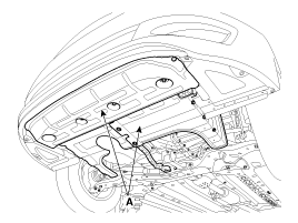
| 7. |
Remove the under cover (A).
|
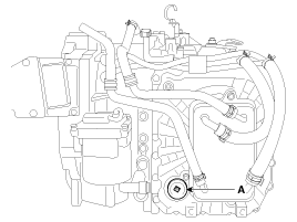
| 8. |
Lift the vehicle, then remove the ATF level plug (A) from the valve body cover.
|

| 9. |
If the ATF flows out of the overflow plug in thin steady
stream, the ATF level is correct. Then finish the procedure and tighten
the ATF plug.
|
| 10. |
Install the under cover (A).
|
| 11. |
Install the eyebolt.
|
| 12. |
Install the air duct (A).
|
| Replacement |
| 1. |
Remove the ATF drain plug (A) and reinstall the ATF drain plug after draining ATF totally.
|
| 2. |
Fill the transaxle with ATF (about 5 liters). |
| 3. |
Check the ATF level.
(Refer to Fluid - "Inspection")
|
 Fluid Components and Components Location
Component Location 1. ATF fill hole (eyebolt) 2. ATF level plug3. ATF drain plug ...
 Valve Body Description and Operation
Description The valve body is essential to automatic transaxle control and consists of various valves used to control the oil feed from the oil pump. Specifically, these valves consist of pressure regulator ...
Other information:
Kia Optima Hybrid (TF HEV) 2016-2020 Service Manual: Front Lower Arm Repair procedures
Replacement 1. Remove the front wheel & tire. Tightening torque: 88.3 ~ 107.9N.m(9.0 ~ 11.0kgf.m, 65.1 ~ 79.6lb-ft) Be careful not to damage to the hub bolts when removing the front wheel & tire. 2. Loosen the bolt & nut and then remove the lower arm (A). Tightening torque: ...
Kia Optima Hybrid (TF HEV) 2016-2020 Service Manual: Head Lamp Leveling Actuator Repair procedures
Inspection with GDS Initialization and diagnosis sequence by using GDS equipment. Below content summarize the procedure for A/S using GDS. No.Procedure1Locate vehicle to flat plane2Tire check3IGN1 ON4Head lamp Low Beam ON5Connection with diagnostic tool6Initial command by diagnostic tool7Clear DTC Code8IGN1 ...