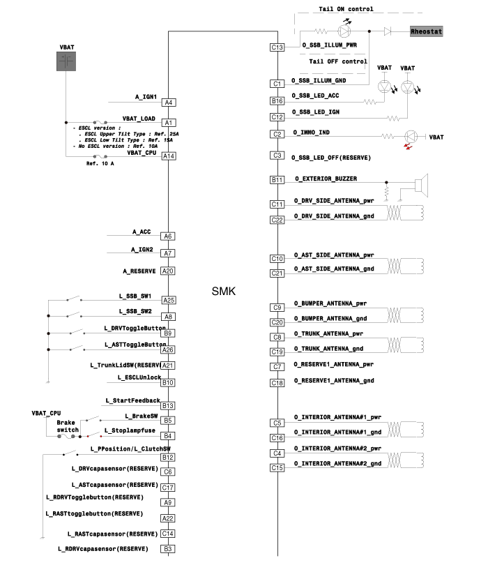
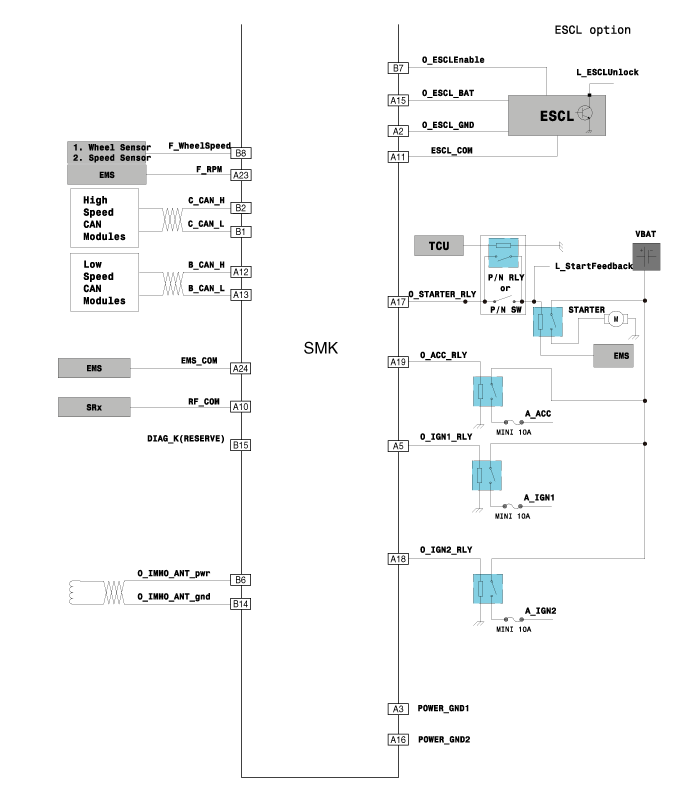
Kia Optima Hybrid: Smart key System / Smart key unit Schematic Diagrams
| Circuit Diagram |


 Smart key unit Components and Components Location
Component (1) Connector Pin Information No.Connector A (26pin)Connector B (16pin)Connector C (22pin)1V_BAT loadC_CAN lowSSB illumination ground2-C_CAN highImmobilzer indicator3Power ground1--4IGN1Stop ...
 Smart key unit Repair procedures
Inspection Smart Key Unit – Refer to the BE group - inspection / self diagnosis with GDS. Smart Key Switch – Refer to the BE group - inspection / self diagnosis with GDS. Antenna – Refer to the BE ...
Other information:
Kia Optima Hybrid (TF HEV) 2016-2020 Service Manual: Repair procedures
Removal Back View Camera 1. Disconnect the negative(-) battery terminal. 2. Open the trunk and remove the trunk door trim. (Refer to the BD group - "Trunk") 3. Disconnect the back view camera connector(A). 4. Pull down and remove the back view camera holder(A). 5. Remove the back view camera (A) after ...
Kia Optima Hybrid (TF HEV) 2016-2020 Service Manual: Body Control Module (BCM) Specifications
Specifications ItemsSpecificationsRated voltageDC 12VOperating voltageDC 9 ~ 16VOperating temperature-22°F~176°F(-30°C~ 80°C)Dark currentBCM & Receiver : 5.5mABCM : 4mA ...
