Kia Optima Hybrid: Seat Electrical / Seat Heater Repair procedures
Kia Optima Hybrid (TF HEV) 2016-2020 Service Manual / Body Electrical System / Seat Electrical / Seat Heater Repair procedures
| Inspection |
First Seat Heater
| 1. |
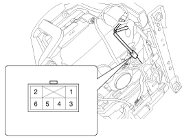
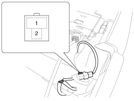
Check for continuity and measure the resistance between No.4 and No.6 terminals.
[Cushion]
[Back]
|
| 2. |
Operate the seat heater after connecting the connector, and
then check the thermostat by measuring the temperature of seat surface.
|
 Seat Heater Schematic Diagrams
Circuit Diagram ...
 Seat Heater (Non-Air Ventilation) Components and Components Location
Component Location ...
Other information:
Kia Optima Hybrid (TF HEV) 2016-2020 Service Manual: Fuel Filler Cap Description and Operation
Description A ratchet tightening device on the threaded fuel filler cap reduces the chances of incorrect installation, which seals the fuel filler. After the gasket on the fuel filler cap and the filler neck flange contact each other, the ratchet produces a loud clicking noise indicating the seal has ...
Kia Optima Hybrid (TF HEV) 2016-2020 Service Manual: Components and Components Location
Component Location Index Engine Room 1. Receiver Drier2. Condenser3. Service Port (High)4. Service Port (Low)5. A/C Pressure Transducer6. Compressor7. Expansion Valve Interior ...
© 2025 Copyright www.koptimatfhev.com


