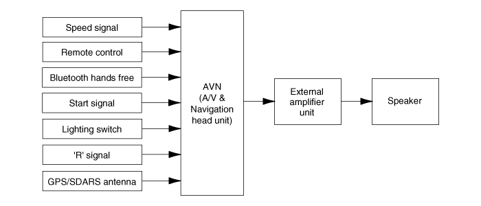
Kia Optima Hybrid: AVN System / Schematic Diagrams
| System Block Diagram |

 Components and Components Location
Components Location 1. AVN (A/V & Navigation head unit)2. Midrange speaker3. External amplifier4. Roof antenna (GPS + SDARS)5. Front door speaker6. Rear speaker7. Woofer speaker8. Antenna feeder cable9. ...
 Description and Operation
Limitations Of The Navigation system GPS Signal Reception State As the GPS satellite frequency is received/transmitted in straight lines, reception may not work if hiding devices are placed on or near ...
Other information:
Kia Optima Hybrid (TF HEV) 2016-2020 Service Manual: Troubleshooting
Troubleshooting SymptomPossible causeRemedyTachometer does not operateCluster fuse (10A) blownCheck for short and replace fuseCAN line faultyCheck the EMSTachometer faultyCheck tachometerWiring or ground faultyRepair if necessaryFuel gauge does not operateCluster fuse (10A) blownCheck for short and replace ...
Kia Optima Hybrid (TF HEV) 2016-2020 Service Manual: Cylinder Block Repair procedures
Disassembly • Use fender covers to avoid damaging painted surfaces. • To avoid damaging the cylinder head, wait until the engine coolant temperature drops below normal temperature before removing it. • When handling a metal gasket, take care not to fold the gasket or damage the contact ...
