Kia Optima Hybrid: Cylinder Block / Cylinder Block Repair procedures
Kia Optima Hybrid (TF HEV) 2016-2020 Service Manual / Engine Mechanical System / Cylinder Block / Cylinder Block Repair procedures
| Disassembly |
|

Mark all wiring and hoses to avoid misconnection. |

| 1. |
Remove the engine and transaxle assembly from the vehicle. (Refer to Engine and transaxle assembly in this group) |
| 2. |
Remove the transaxle assembly. (Refer to AT group) |
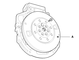
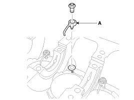
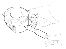
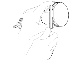
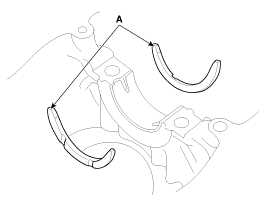
| 3. |
Remove the torsion damper (A).
|
| 4. |
Install the engine to an engine stand for disassembly. |
| 5. |
Remove the intake manifold and exhaust manifold. (Refer to Intake and exhaust system in this group) |
| 6. |
Remove the timing chain. (Refer to Timing system in this group) |
| 7. |
Remove the cylinder head assembly. (Refer to Cylinder head in this group) |
| 8. |
Remove the balance shaft & oil pump assembly. (Refer to Lubrication system in this group) |
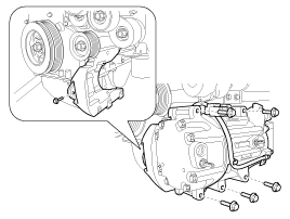
| 9. |
Remove the A/C compressor and bracket assembly. (Refer to HA group - "Electric A/C compressor")
|
| 10. |
Remove the hybrid starter generator (HSG). (Refer to HT group - "Hybrid starter generator") |
| 11. |
Remove the water pump assembly. (Refer to Cooling system in this group) |
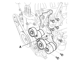
| 12. |
Remove the tensioner assembly integrated bracket (A).
|
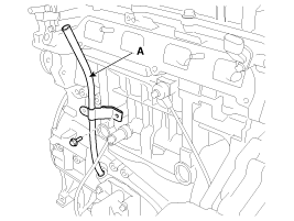
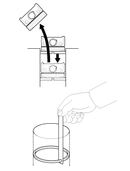
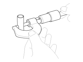
| 13. |
Remove the oil level gauge tube (A).
|
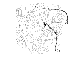
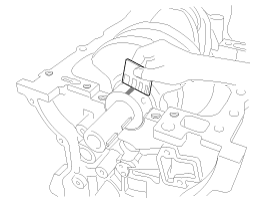
| 14. |
Remove the knock sensor (A) and the oil pressure switch (OPS) (B).
|
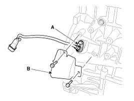
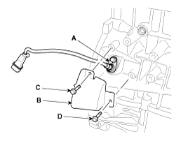
| 15. |
Remove the crankshaft position sensor (CKPS) (A) after removing the cover (B).
|
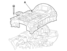
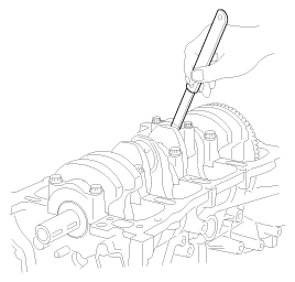
| 16. |
Remove the ladder frame (A).
|
| 17. |
Check the connecting rod end play. |
| 18. |
Remove the connecting rod caps and check oil clearance. |
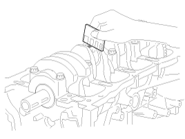
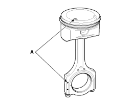
| 19. |
Remove piston and connecting rod assemblies.
|
| 20. |
Remove crankshaft bearing cap and check oil clearance. |
| 21. |
Check the crankshaft end play. |
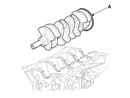
| 22. |
Lift the crankshaft (A) out of the engine, being careful not to damage journals.
|
| 23. |
Remove the oil jet (A).
|
| 24. |
Check fit between piston and piston pin.
Try to move the piston back and forth on the piston pin. If any movement is felt, replace the piston and pin as a set. |
| 25. |
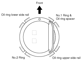
Remove piston rings.
|
| 26. |
Remove the snap rings and then disconnect the connecting rod from the piston. |
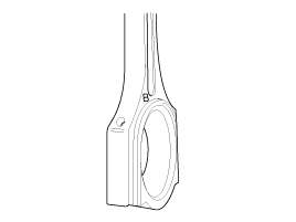
| Inspection |
Connecting Rod
| 1. |
Check the connecting rod end play.
Using a feeler gauge, measure the end play while moving the connecting rod back and forth.
|
| 2. |
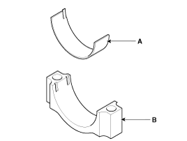
Check the connecting road bearing oil clearance.
|
| 3. |
Inspect the connecting rods.
|
Crankshaft
| 1. |
Check the crankshaft bearing oil clearance.
|
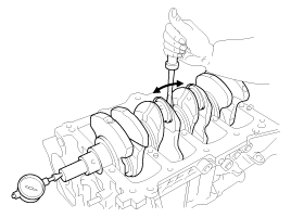
| 2. |
Check crankshaft end play.
Using a dial indicator, measure the thrust clearance while prying the crankshaft back and forth with a screwdriver.
If the end play is greater than maximum, replace the thrust bearings as a set.
|
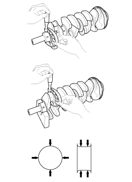
| 3. |
Inspect main journals and crank pins.
Using a micrometer, measure the diameter of each main journal and crank pin.
|
Cylinder Block
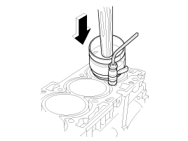
| 1. |
Remove gasket material.
Using a gasket scraper, remove all the gasket material from the top surface of the cylinder block. |
| 2. |
Clean cylinder block
Using a soft brush and solvent, thoroughly clean the cylinder block. |
| 3. |
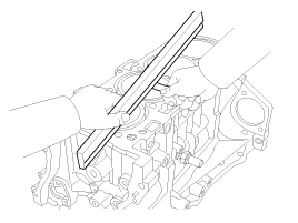
Inspect top surface of cylinder block for flatness.
Using a precision straight edge and feeler gauge, measure the surface contacting the cylinder head gasket for warpage.
|
| 4. |
Inspect cylinder bore diameter.
Visually check the cylinder for vertical scratchs.
If deep scratches are present, replace the cylinder block. |
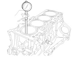
| 5. |
Inspect cylinder bore diameter.
Using a cylinder bore gauge, measure the cylinder bore diameter at position in the thrust and axial directions.
|
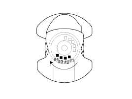
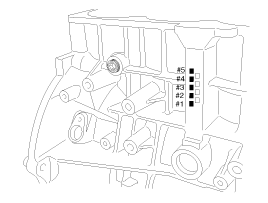
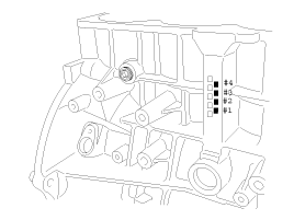
| 6. |
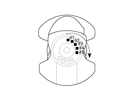
Check the cylinder bore size code on the cylinder block.
Cylinder Bore Inner Diameter
|
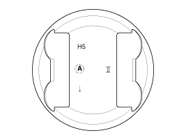
| 7. |
Check the piston size code on the piston top face.
H5 : HEV 2.4L
A : Grade
II : Theta II
Piston Outer Diameter
|
| 8. |
Select the piston related to cylinder bore class.
|
Piston And Rings
| 1. |
Clean piston
|
| 2. |
The standard measurement of the piston outside diameter is taken 17mm (0.67in.) from the bottom of the piston.
|
| 3. |
Calculate the difference between the cylinder bore diameter and the piston diameter.
|
| 4. |
Inspect the piston ring side clearance.
Using a feeler gauge, measure the clearance between new piston ring and the wall of the ring groove.
If the clearance is greater than maximum, replace the piston. |
| 5. |
Inspect piston ring end gap.
To measure the piston ring end gap, insert a piston ring into
the cylinder bore. Position the ring at right angles to the cylinder
wall by gently pressing it down with a piston. Measure the gap with a
feeler gauge. If the gap exceeds the service limit, replace the piston
ring. If the gap is too large, recheck the cylinder bore diameter
against the wear limits, If the bore is over the service limit, the
cylinder block must be replaced.
|
Piston Pins
| 1. |
Measure the diameter of the piston pin.
|
| 2. |
Measure the piston pin-to-piston clearance.
|
| 3. |
Check the clearance between the piston pin diameter and the connecting rod small end diameter.
|
| Reassembly |
|
| 1. |
Assemble the piston and connecting rod.
|
| 2. |
Install the piston rings.
|
| 3. |
Install the connecting rod bearings.
|
| 4. |
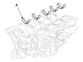
Install the main bearings.
|
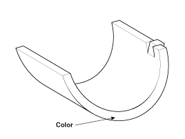
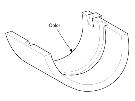
| 5. |
Install the thrust bearings.
Install the 2 thrust bearings(A) under the No.3 journal position of the cylinder block with the oil grooves facing outward.
|
| 6. |
Install the oil jet (A).
|
| 7. |
Place the crankshaft(A) on the cylinder block.
|
| 8. |
Place the main bearing caps on cylinder block. |
| 9. |
Install the main bearing cap bolts.
|
| 10. |
Check crankshaft end play. |
| 11. |
Install piston and connecting rod assemblies.
|
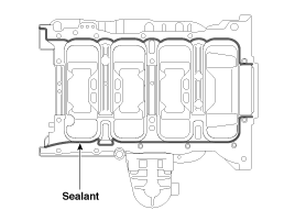
| 12. |
Apply liquid gasket to the mating surface of cylinder block and ladder frame.
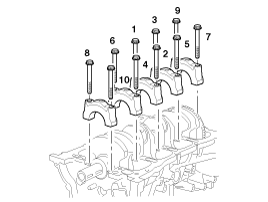
|
| 13. |
Install ladder frame (A) with 10 bolts, in several passes, in sequence shown.
|
| 14. |
Install rear oil seal.
|
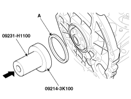
| 15. |
Install CKPS (Crankshaft position sensor) (A) and sensor cover (B).
|
| 16. |
Install OPS (Oil pressure switch).
|
| 17. |
Install knock sensor (A).
|
| 18. |
Install oil level gauge assembly.
|
| 19. |
Install tensioner assembly integrated bracket (A).
|
| 20. |
Install the water pump. (Refer to Cooling system in this group) |
| 21. |
Install the HSG (Hybrid starter generator). (Refer to HT group - "Hybrid starter generator") |
| 22. |
Install the A/C compressor and bracket assembly. (Refer to HA group - "Electric A/C compressor")
|
| 23. |
Install the balance shaft & oil pump assembly. (Refer to Lubrication system in this group) |
| 24. |
Install the cylinder head assembly. (Refer to Cylinder head in this group) |
| 25. |
Install the timing chain. (Refer to Timing system in this group) |
| 26. |
Install the intake manifold and exhaust manifold.
(Refer to Intake and exhaust system in this group) |
| 27. |
Remove the engine from the engine stand. |
| 28. |
Install the torsion damper (A).
|
| 29. |
Install the transaxle assembly. (Refer to AT group - "Automatic transaxle") |
| 30. |
Install the engine and transaxle assembly on the vehicle. (Refer to Engine and transaxle assembly in this group) |
| 31. |
Installation is in the reverse order of removal.
Add all the necessary fluids and check for leaks. Connect GDS. Check for codes, note, and clear. Recheck.
|
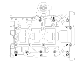
 Cylinder Block Components and Components Location
Components 1. Piston ring2. Piston3. Connecting rod 4. Connecting rod upper bearing5. Piston pin6. Connecting rod lower bearing7. Connecting rod bearing cap8. Ladder frame9. Oil filter bracket10. Crankshaft ...
 Cooling System
...
Other information:
Kia Optima Hybrid (TF HEV) 2016-2020 Service Manual: TPMS Receiver Schematic Diagrams
Circuit Diagram Connector pin number Pin NO.DiscriptionRemark1-2-3ECU battery terminal4-5CAN_High6CAN_Low7-8-9Ground10-11-12-13-14-15-16-17-18Ignition ON19-20- ...
Kia Optima Hybrid (TF HEV) 2016-2020 Service Manual: Description and Operation
Description System Overview The System offers the following features: – Human machine interface through a 1-stage button, for terminal switching and engine start. – Control of external relays for ACC / IGN1 / IGN2 terminal switching and STARTER, without use of mechanical ignition switch. – Indication ...
© 2025 Copyright www.koptimatfhev.com