Kia Optima Hybrid: Fuses And Relays / Relay Box (Passenger Compartment) Repair procedures
Kia Optima Hybrid (TF HEV) 2016-2020 Service Manual / Body Electrical System / Fuses And Relays / Relay Box (Passenger Compartment) Repair procedures
| Fuse Inspection |
| 1. |
Be sure there is no play in the fuse holders, and that the fuses are held securely. |
| 2. |
Are the fuse capacities for each circuit correct? |
| 3. |
Are there any blown fuses?
If a fuse is to be replaced, be sure to use a new fuse of the
same capacity. Always determine why the fuse blew first and completely
eliminate the problem before installing a new fuse. |
| Inspection |
| 1. |
The SJB can be diagnosed by using the GDS. The SJB
communicates with the GDS which then displays inputs and outputs along
with codes. |
| 2. |
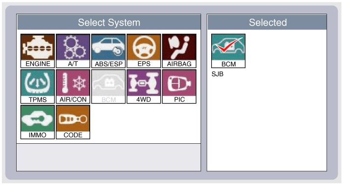
To diagnose the SJB function, select the vehicle model, BCM and SJB.
|
| 3. |
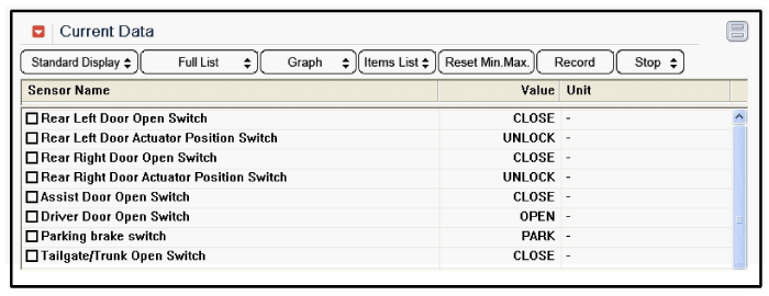
To consult the present input/out value of SJB, "Current DATA". It provides information of SJB input/output conditions.
|
| 4. |
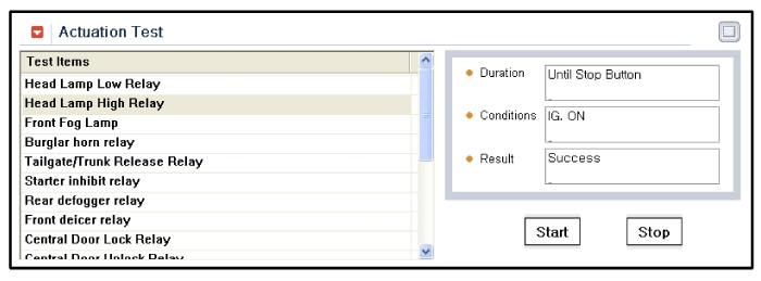
To perform functional test on SJB outputs, select "Actuation Test"
|
| Removal |
Passenger Compartment Junction Box (SJB)
| 1. |
Disconnect the negative(-) battery terminal. |
| 2. |
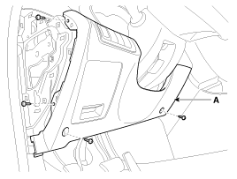
Remove the crash pad lower panel (A).
(Refer to the BD group - "Crash pad")
|
| 3. |
Disconnect the connectors (A) from the fuse side of the smart junction box.
|
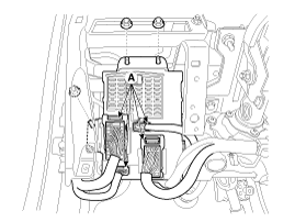
| 4. |
Remove the smart junction box after loosening the mounting nuts (2EA). |
| 5. |
Disconnect the connectors from the back side of the smart junction box. |
| Installation |
| 1. |
Install the smart junction box. |
| 2. |
Install the crash pad lower panel. |
| 3. |
Check that all system operates normally. |


Other information:
Kia Optima Hybrid (TF HEV) 2016-2020 Service Manual: Front Strut Assembly Repair procedures
Replacement 1. Remove the front wheel & tire. Tightening torque: 88.3 ~ 107.9N.m(9.0 ~ 11.0kgf.m, 65.1 ~ 79.6lb-ft) Be careful not to damage to the hub bolts when removing the front wheel & tire. 2. Remove the wheel speed sensor (B) from the front strut assembly by loosening mounting ...
Kia Optima Hybrid (TF HEV) 2016-2020 Service Manual: Components and Components Location
Component Location 1. Seat Memory Unit (IMS)2. IMS control switch3. IMS driver power seat control ...
© 2025 Copyright www.koptimatfhev.com