Kia Optima Hybrid: Seat Electrical / Power Seat Motor Repair procedures
| Inspection |
| 1. |
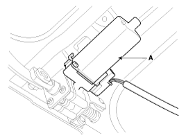
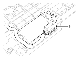
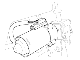
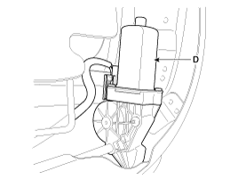
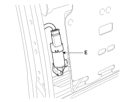
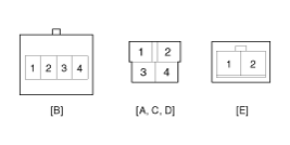
Disconnect the connectors for each motor.
A : Front height motor
B : Slide motor
C : Rear height motor
D : Recline motor
E : Lumber support motor
|
| 2. |
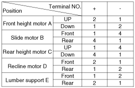
With the battery connected directly to the motor terminals, check if the motors run smoothly. |
| 3. |
Reverse the connections and check that the motor rotates in reverse. |
| 4. |
If there is an abnormality, replace the motors.
|
| 1. |
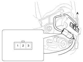
Disconnect the limit switch and operate the limit switch. |
| 2. |
Check for continuity between the terminals. |
| 3. |
Make sure that the seat operation is normal in the reverse after the maximum operation. |
| 4. |
If there is an abnormality, replace the limit switch.
|
 Components and Components Location
Component Location 1. Slide motor2. Front height motor3. Rear height motor4. Lumber support motor5. Power seat control switch6. Recline motor7. Recline control switch8. Lumber support switch ...
 Power Seat Control Switch Schematic Diagrams
Circuit Diagram ...
Other information:
Kia Optima Hybrid (TF HEV) 2016-2020 Service Manual: Cruise Control Switch Repair procedures
Removal and Installation 1. Disconnect the battery negative terminal. Tightening torque : 4.0 ~ 6.0N.m (0.4 ~ 0.6kgf.m, 3.0 ~ 4.4lb-ft) 2. Remove the driver airbag module. (Refer to the RT group - "Airbag module") 3. Remove the steering wheel. (Refer to the ST group - "Steering column and shaft") 4. ...
Kia Optima Hybrid (TF HEV) 2016-2020 Service Manual: Description and Operation
Description Regeneration Brake System During deceleration or braking of an electric vehicle or HEV, the drive motor acts as an alternator and charges the battery by converting the vehicle’s kinetic energy generated during braking into electrical energy. Regenerative braking amount depends on the vehicle ...

