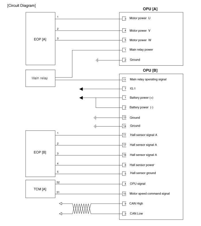
Kia Optima Hybrid: Hydraulic System / Oil Pump Uni t(OPU) Schematic Diagrams
| OPU connector and terminal function |

| OPU terminal function |
| Pin | Description |
| 1 | Main relay power |
| 2 | Ground |
| 3 | Motor phase power(U) |
| 4 | Motor phase power(V) |
| 5 | Motor phase power(W) |
| Pin | Description |
| 1 | Battery power (+) |
| 2 | Battery power (+) |
| 3 | CAN communication line (Low) |
| 4 | OPU status signal |
| 5 | Hall sensor ground |
| 6 | Hall sensor power(+5V) |
| 7 | IG_Key |
| 9 | CAN communication line (HIGH) |
| 11 | Hall signal A |
| 12 | Main relay operation signal |
| 13 | Ground |
| 14 | Ground |
| 15 | Motor speed command signal |
| 17 | Hall signal B |
| 18 | Hall signal C |
| OPU Terminal input/ output signal |
| Pin | Description | Condition | Input/output value | |
| Type | Level | |||
| 1 | Main relay power | IG Off ------------------ After startup (Disable) ------------------ After startup (Enable) | DC Voltage | - -------------------- Max. 0.5V -------------------------- Battery Voltage |
| 2 | Ground | IG Off ------------------ IG On | DC Voltage | - -------------------- Max. 0.5V |
| 3 | Motor phase power (U) | IG Off ------------------ After startup (Disable) ------------------ After startup (Enable) | PWM | - -------------------- Max. 0.5V -------------------------- Battery Voltage |
| 4 | Motor phase power (V) | IG Off ------------------ After startup (Disable) ------------------ After startup (Enable) | PWM | - -------------------- Max. 0.5V -------------------------- Battery Voltage |
| 5 | Motor phase power (W) | IG Off ------------------ After startup (Disable) ------------------ After startup (Enable) | PWM | - -------------------- Max. 0.5V -------------------------- Battery Voltage |
| Pin | Description | Condition | Input/output value | |
| Type | Level | |||
| 1 | Battery power (+) | IG Off ------------------ After startup ------------------ Startup Off(dark current) | DC Voltage | Battery Voltage -------------------- Battery Voltage -------------------- Max 5mA |
| 2 | Battery power(+) | IG Off ------------------ After startup ------------------ Startup off(dark current) | DC Voltage | Battery Voltage -------------------- Battery Voltage -------------------- Max 5mA |
| 3 | CAN Low | IG Off ------------------ Recessive ------------------ Dominant | Pulse | - -------------------- 2.0 ~ 3.0 V -------------------- 0.5~2.25 V |
| 4 | OPU status signal | IG Off ------------------ After startup (Low) ------------------ After startup (High) | Pulse | - -------------------- Max. 1.0V -------------------------- 0V / Battery voltage level 9V < Battery voltage level <16V |
| 5 | Hall sensor ground | IG Off ------------------ IG On | DC Voltage | - -------------------- Max. 0.5V |
| 6 | Hall sensor power(+5V) | IG Off ------------------ IG On | DC Voltage | - -------------------- 5.0V ± 0.5V |
| 7 | IG_Key | IG Off ------------------ IG On | DC Voltage | - -------------------- Battery Voltage |
| 9 | CAN High | IG Off ------------------ Recessive ------------------ Dominant | Pulse | - -------------------- 2.0 ~ 3.0 V -------------------- 2.75~4.5 V |
| 11 | Hall signal A | IG Off ------------------ After startup (Low) ------------------ After startup (High) | Pulse | - -------------------- Max. 0.5V -------------------------- 5.0V ± 0.5V |
| 12 | Main relay operation signal | IG Off ------------------ After startup(Disable) ------------------ After startup (Enable) | DC Voltage | - -------------------- Battery voltage level -------------------------- Battery voltage level |
| 13 | Ground | IG Off ------------------ IG On | DC Voltage | - -------------------- Max. 0.5V |
| 14 | Ground | IG Off ------------------ IG On | DC Voltage | - -------------------- Max. 0.5V |
| 15 | Motor speed command signal | IG Off ------------------ After startup (Low) ------------------ After startup (High) | Pulse | - -------------------- Max. 0.5V -------------------------- 0V / Battery voltage level 9V < Battery voltage level <16V |
| 17 | Hall signal B | IG Off ------------------ After startup (Low) ------------------ After startup (High) | Pulse | - -------------------- Max. 0.5V -------------------------- 5.0V ± 0.5V |
| 18 | Hall signal C | IG Off After startup (Low) ------------------ After startup (High) | Pulse | - -------------------- Max. 0.5V -------------------------- 5.0V ± 0.5V |
| Circuit Diagram |

 Oil Pump Uni t(OPU) Components and Components Location
Components Location 1. Oil Pump Unit (OPU) ...
 Oil Pump Uni t(OPU) Repair procedures
Removal 1. Disconnect the 12V battery negative (-) cable. 2. Remove the under cover (A). 3. Remove the wiring fixed clip at bracket after removing oil pump connector (A). Tightening torque: 18.6 ~ 27.5 ...
Other information:
Kia Optima Hybrid (TF HEV) 2016-2020 Service Manual: Troubleshooting
Troubleshooting SymptomSuspect AreaRemedy (Refer to page)Water leaks from sunroofDeteriorated roof lid weatherstripReplaceExcessive roof lid-to-body clearance and improperly fitted weatherstripAdjustWind noise around sunroofLoose or deformed deflector, gaps in body workRe-tighten adjust or replaceNoise ...
Kia Optima Hybrid (TF HEV) 2016-2020 Service Manual: Auto Head Lamp Leveling Unit Repair procedures
Inspection 1. Ignition "ON". 2. Turn on the head lamp switch. 3. Check for operation. If the aim of the head lamps changes smoothly when the head lamp leveling switch is turned. 4. If the operation does not work well, inspect the connector and terminals to be sure they are all making good contact. If ...
