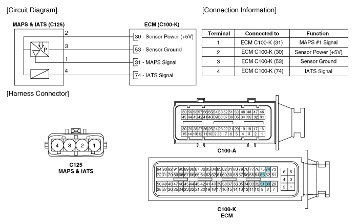
Kia Optima Hybrid: Engine Control System / Manifold Absolute Pressure Sensor (MAPS) Schematic Diagrams
| Circuit Diagram |

 Manifold Absolute Pressure Sensor (MAPS) Repair procedures
Inspection 1. Connect the GDS on the Data Link Connector (DLC). 2. Measure the output voltage of the MAPS at idle and IG ON. Test ConditionOutput Voltage (V)IG ON3.9 ~ 4.1Idle0.8 ~ 1.6 Removal 1. Turn ...
Other information:
Kia Optima Hybrid (TF HEV) 2016-2020 Service Manual: Turn Signal Lamp Repair procedures
Removal Door Mirror Turn Signal Lamp 1. Disconnect the negative (-) battery terminal. 2. Remove the mirror (C) after disconnecting the heater connector (A) and BSD warning connector (B). 3. Remove the door mirror housing (A) after loosening the mounting screw. Take care not to damage the ...
Kia Optima Hybrid (TF HEV) 2016-2020 Service Manual: Repair procedures
Diagnosis With GDS 1. BSD system defects can be quickly diagnosed with the GDS. GDS operates actuator quickly to monitor, input/output value and self diagnosis. 2. Connect the cable of GDS to the data link connector in driver side crash pad lower panel, turn the power on GDS. 3. Select the vehicle model ...

