Kia Optima Hybrid: Lighting System / Turn Signal Lamp Repair procedures
| Removal |
| 1. |
Disconnect the negative (-) battery terminal. |
| 2. |
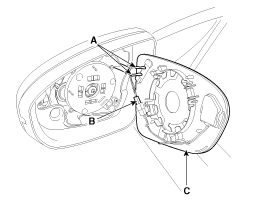
Remove the mirror (C) after disconnecting the heater connector (A) and BSD warning connector (B).
|
| 3. |
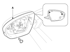
Remove the door mirror housing (A) after loosening the mounting screw.
|
| 4. |
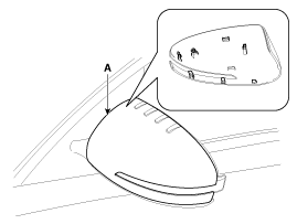
Remove the door mirror cover (A) after removing the fixing clip.
|
| 5. |
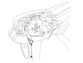
Loosen the mounting screw (A).
|
| 6. |
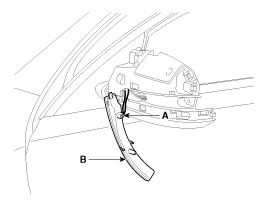
Remove the door mirror turn signal lamp (B) after disconnecting the connector (A).
|
| Installation |
| 1. |
Install the bulb to the side repeater lamp assembly. |
| 2. |
Install the side repeater lamp. |
| 1. |
Install the door mirror turn signal lamp to the door mirror. |
| 2. |
Install the door mirror. |
| 3. |
Connect the battery terminal (-). |
 Rear combination lamp Repair procedures
Removal Rear Combination lamp (Outside) 1. Disconnect the negative (-) battery terminal. 2. Remove the rear combination lamp cover (A). 3. Replace the turn signal lamp bulbs (A) by turning it counterclockwise. ...
 Troubleshooting
Troubleshooting 1. The lamp switch inputs can be checked using the GDS. 2. To check the input value of lamp switch, select option "Body Control Module". 3. To consult the present input/output value of ...
Other information:
Kia Optima Hybrid (TF HEV) 2016-2020 Service Manual: Heated Oxygen Sensor (HO2S) Description and Operation
Description Heated Oxygen Sensor (HO2S) consists of zirconium and alumina and is installed both upstream and downstream of the Catalytic Converter. It varies in accordance with the air/fuel ratio. The sensor must be hot in order to operate normally. To keep it hot, the sensor has a heater which is controlled ...
Kia Optima Hybrid (TF HEV) 2016-2020 Service Manual: High Voltage Shut-off Procedures
High Voltage Shut-off Procedures Be sure to read and follow the “General Safety Information and Caution” before doing any work related with the high voltage system. Failure to follow the safety instructions may result in serious electrical injuries. • High voltage components: ...

