Kia Optima Hybrid: Engine Control System / Manifold Absolute Pressure Sensor (MAPS) Repair procedures
| Inspection |
| 1. |
Connect the GDS on the Data Link Connector (DLC). |
| 2. |
Measure the output voltage of the MAPS at idle and IG ON.
|
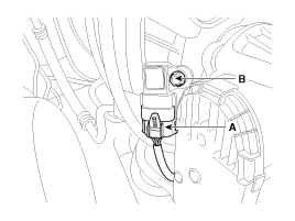
| Removal |
| 1. |
Turn the ignition switch OFF and disconnect the battery negative (-) terminal. |
| 2. |
Disconnect the manifold absolute pressure sensor connector (A). |
| 3. |
Remove the mounting bolt (B), and then remove the sensor from the surge tank.
|
| Installation |
|

| 1. |
Install in the reverse order of removal.
|
 Manifold Absolute Pressure Sensor (MAPS) Schematic Diagrams
Circuit Diagram ...
 Intake Air Temperature Sensor (IATS) Description and Operation
Description Intake Air Temperature Sensor (IATS) is included inside Manifold Absolute Pressure Sensor and detects the intake air temperature. To calculate precise air quantity, correction of the air temperature ...
Other information:
Kia Optima Hybrid (TF HEV) 2016-2020 Service Manual: Special Service Tools
Special Service Tools Tool Name / NumberIllustrationDescriptionBand installer09495 - 39100Installation of hook type boot band.Band installer09495 - 3K000Installation of ear type boot bandLower arm ball joint remover0K545-A9100Removal of front lower arm from front axle Personal Protective Equipment NameIllustrationDescriptionInsulation ...
Kia Optima Hybrid (TF HEV) 2016-2020 Service Manual: Power Window Switch Repair procedures
Inspection Power Window Main Switch Inspection 1. Disconnect the negative (-) battery terminal. 2. Remove the front door trim panel. (Refer to the BD group - "Front door") 3. Disconnect the connector from the switch. 4. Check for continuity between the terminals in each switch position according to the ...