Kia Optima Hybrid: Body Dimensions / Interior Body Repair
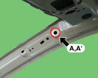
| Interior A |
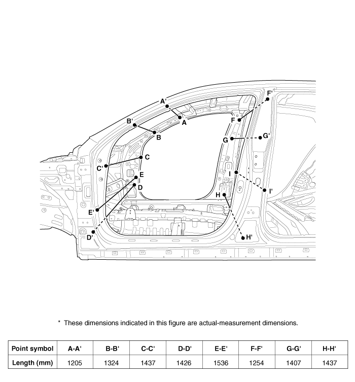
|
|
|
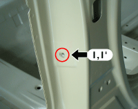
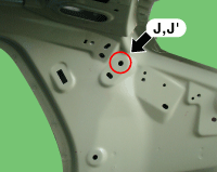
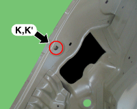
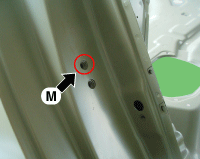
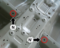
| Front pillar trim mounting hole (O12) | Front pillar trim mounting hole (O8.4) | Cowl crossbar mounting hole (O9) |
|
|
|
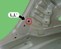
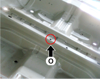
| Cowl side trim mounting hole (8.4X8.4) | Front door checker mounting hole (O13) | Seat belt height adjust upper mounting hole (O12) |
|
| |
| Seat belt height adjust upper mounting hole (O12) | Front seat belt retractor mounting hole (O12) |
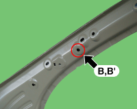
| Interior B |
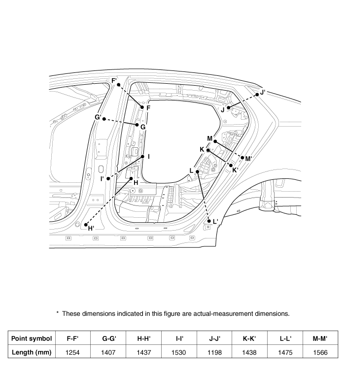
|
|
|
| Seat belt height adjust upper mounting hole (O12) | Seat belt height adjust upper mounting hole (O12) | Front seat belt retractor mounting hole (O12) |
|
|
|
| Rear door checker mounting hole (O13) | Rear pillar trim mounting hole (O8.4) | Quarter inner panel tooling hole (O16) |
|
| |
| Wheel house panel tooling hole (O12) | Rear door striker mounting hole (O13) |
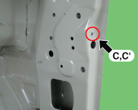
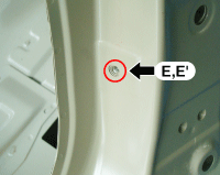
| Interior C |
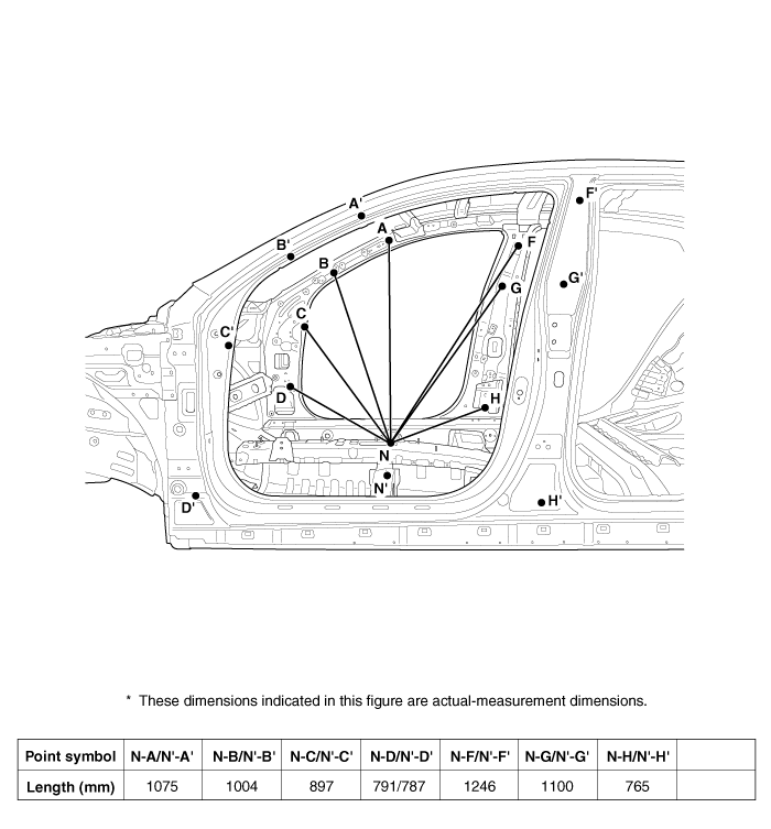
|
|
|
| Front pillar trim mounting hole (O12) | Front pillar trim mounting hole (O8.4) | Cowl crossbar mounting hole (O9) |
|
|
|
| Cowl side trim mounting hole (8.4X8.4) | Seat belt height adjust upper mounting hole (O12) | Seat belt height adjust upper mounting hole (O12) |
|
| |
| Front seat belt retractor mounting hole (O12) | Front seat mounting hole (O11) |
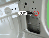
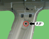
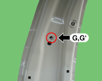
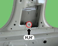
| Interior D |
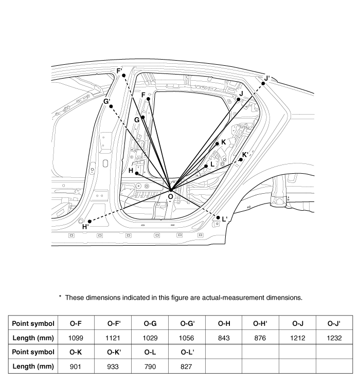
|
|
|
| Seat belt height adjust upper mounting hole (O12) | Seat belt height adjust lower mounting hole (O12) | Front seat belt retractor mounting hole (O12) |
|
|
|
| Rear pillar trim mounting hole (O8.4) | Quarter inner panel tooling hole (O16) | Wheel house panel tooling hole (O12) |
| ||
| Rear floor tooling hole (O15) |
 Side Body Body Repair
Side Body A Front side member tooling hole (O20)Fender apron tooling hole (O10)Front door upper hinge mounting hole (O13)Front door lower hinge mounting hole (O13)Fender panel mounting hole (O6.6)Rear ...
 Rear Body Body Repair
Side outer panel rear cornerRear package tray trim mounting hole (O10)Rear transverse trim mounting hole (O8.4)Rear combination lamp mounting hole (8.5X8.5)Rear bumper mounting hole (11X13) ...
Other information:
Kia Optima Hybrid (TF HEV) 2016-2020 Service Manual: Anchor Pretensioner (APT) Repair procedures
Removal 1. Disconnect the battery negative cable, and wait for at least three minutes before beginning work. 2. To remove the seat belt anchor pretensioner (C), keep on pushing the lock pin (A) as arrow direction. And then remove the seat belt after pushing the lock pin (B). 3. Remove the door scuff ...
Kia Optima Hybrid (TF HEV) 2016-2020 Service Manual: Oil Pump Uni t(OPU) Specifications
Specifications Operating voltage (V)12 Current15 ~ 20A (normal), 45A (Max.) ...

