Kia Optima Hybrid: Cooling System / Water pump Repair procedures
| Removal and Installation |
| 1. |
Loosen the drain plug, and then drain the engine coolant. Remove the radiator cap to help drain the coolant faster. |
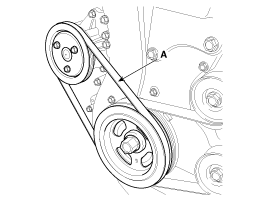
| 2. |
Remove the water pump drive belt (A).
When installing the water pump drive belt,
|
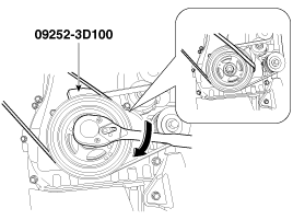
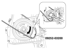
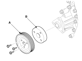
| 3. |
Remove the water pump pulley (A) and the dust cover (B).
|
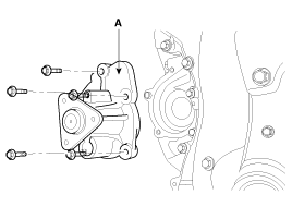
| 4. |
Remove the water pump (A) with the gasket.
|
| 5. |
Remove the exhaust manifold heat protector. (Refer to Intake and exhaust system) |
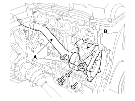
| 6. |
Remove the water pump cover (B) with the gasket and the water inlet pipe (A).
|
| 7. |
Installation is reverse order of removal with a new water pump gasket. |
| 8. |
Fill the engine coolant. |
| 9. |
Start the engine and check for leaks. |
| 10. |
Recheck the coolant level. |
| Inspection |
| 1. |
Check each part for cracks, damage or wear, and replace the coolant pump assembly if necessary. |
| 2. |
Check the bearing for damage, abnormal noise and sluggish rotation, and replace the coolant pump assembly if necessary. |
| 3. |
Check for coolant leakage. If coolant leaks from hole, the seal is defective. Replace the coolant pump assembly.
|

 Water pump Components and Components Location
Components 1. Water pump pulley2. Dust cover3. Water pump sub assembly (Water pump housing)4. Water pump housing gasket5. Water pump cover6. Water pump gasket7. Water inlet pipe gasket (O-ring)8. Water ...
 Water pump Troubleshooting
Troubleshooting SymptomsPossible CausesRemedyCoolant leakage • From the bleed hole of the water pump Visually check • Check leaks after about ten-minute warming up. • If coolant still leaks, replace ...
Other information:
Kia Optima Hybrid (TF HEV) 2016-2020 Service Manual: Power Window Switch Repair procedures
Inspection Power Window Main Switch Inspection 1. Disconnect the negative (-) battery terminal. 2. Remove the front door trim panel. (Refer to the BD group - "Front door") 3. Disconnect the connector from the switch. 4. Check for continuity between the terminals in each switch position according to the ...
Kia Optima Hybrid (TF HEV) 2016-2020 Service Manual: Mode Control Actuator Repair procedures
Inspection 1. Ignition "OFF” 2. Disconnect the connector of mode control actuator. 3. Verify that the mode control actuator operates to the defrost mode when connecting 12V to the terminal 3and grounding terminal 7. 4. Verify that the mode control actuator operates to the vent mode when connecting ...