Kia Optima Hybrid: IMS (Integrated Memory) / IMS Power Seat Control Schematic Diagrams
| Circuit diagram |
 IMS (Integrated Memory System) module Repair procedures
Removal 1. Remove the negative (-) battery terminal. 2. Remove the driver seat in the car. (Refer to the BD group - "Front seat") 3. Remove the IMS module (A) after loosening 3 screws in the bottom of ...
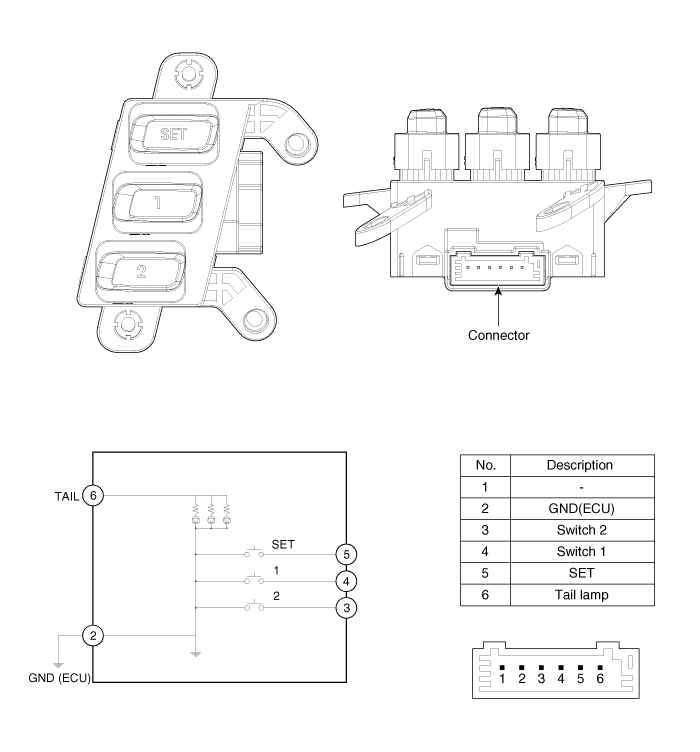
 IMS Power Seat Control Repair procedures
Inspection 1. Disconnect the IMS control switch connector. 2. With the power IMS control switch in each position, make sure that continuity exists between the terminals below. If continuity is not as specified, ...
Other information:
Kia Optima Hybrid (TF HEV) 2016-2020 Service Manual: Tire Repair procedures
Tire wear 1. Measure the tread depth of the tires. Tread depth [limit] : 1.6 mm (0.063 in.) 2. If the remaining tread depth (A) is less than the limit, replace the tire. When the tread depth of the tires is less than 1.6 mm(0.063 in.), the wear indicators (B) will appear. ...
Kia Optima Hybrid (TF HEV) 2016-2020 Service Manual: CVVT Oil Control Valve (OCV) Description and Operation
Description Continuous Variable Valve Timing (CVVT) system advances or retards the valve timing of the intake and exhaust valve in accordance with the ECM control signal which is calculated by the engine speed and load. By controlling CVVT, the valve over-lap or under-lap occurs, which makes better fuel ...