Kia Optima Hybrid: Intake And Exhaust System / Exhaust Manifold Repair procedures
| Removal and Installation |
| 1. |
Remove the engine cover. |
| 2. |
Disconnect the battery negative terminal.
|
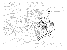
| 3. |
Disconnect the oxygen sensor connectors (A).
|
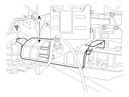
| 4. |
Remove the front muffler (A).
|
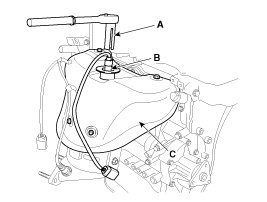
| 5. |
Using the SST (09392-2H100) (A), remove the front oxygen sensor (B) and the remove the exhaust manifold heat protector (C).
|
| 6. |
Remove the driveshaft heat protector (A).
|
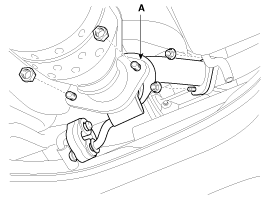
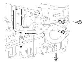
| 7. |
Remove the exhaust manifold stay (A).
|
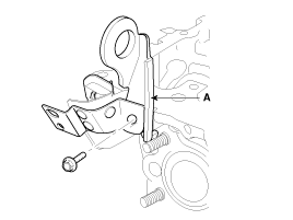
| 8. |
Remove the engine hanger and cam position sensor cover (A).
|
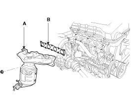
| 9. |
Remove the exhaust manifold (A) with the gasket (B).
When installing the intake manifold, tighten the nuts with
pre-torque first, and then tighten the nuts with specified torque in the
sequence shown.
|

| 10. |
Installation is reverse order of removal. |
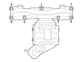
 Exhaust Manifold Components and Components Location
Components 1. Heat protector2. Exhaust manifold3. Exhaust manifold gasket4. Exhaust manifold stay ...
 Muffler Components and Components Location
Components 1. Front muffler2. Catalytic converter3. Center muffler4. Main muffler5. Gasket6. Hanger ...
Other information:
Kia Optima Hybrid (TF HEV) 2016-2020 Service Manual: High Voltage Shut-off Procedures
High Voltage Shut-off Procedures Be sure to read and follow the “General Safety Information and Caution” before doing any work related with the high voltage system. Failure to follow the safety instructions may result in serious electrical injuries. • High voltage components: ...
Kia Optima Hybrid (TF HEV) 2016-2020 Service Manual: NVLD(Natural Vacuum Leakage Detection) Description and Operation
Description NVLD(Natural Vacuum Leakage Detection) is located between the canister and the fuel tank air filter. NVLD is to detect leaks equivalent to a 0.5 mm hole in the fuel tank, canister and hoses. When the engine has been running, the temperature of the fuel in the fuel tank is raised slightly. ...