Kia Optima Hybrid: Engine Control System / ETC (Electronic Throttle Control) System Specifications
Kia Optima Hybrid (TF HEV) 2016-2020 Service Manual / Engine Control/Fuel System / Engine Control System / ETC (Electronic Throttle Control) System Specifications
| Specification |
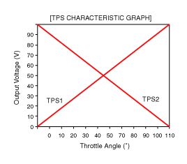
[Throttle Position Sensor (TPS)]
| Throttle Angle(°) | Output Voltage(V) | |
| TPS1 | TPS2 | |
| 0 | 0.0 | 5.0 |
| 10 | 0.48 | 4.52 |
| 20 | 0.95 | 4.05 |
| 30 | 1.43 | 3.57 |
| 40 | 1.90 | 3.10 |
| 50 | 2.38 | 2.62 |
| 60 | 2.86 | 2.14 |
| 70 | 3.33 | 1.67 |
| 80 | 3.81 | 1.19 |
| 90 | 4.29 | 0.71 |
| 100 | 4.76 | 0.24 |
| 105 | 5.0 | 0 |
| C.T (6 ~ 15°) | 0.29 ~ 0.71 | 4.29 ~ 4.71 |
| W.O.T (93 ~ 102°) | 4.43 ~ 4.86 | 0.14 ~ 0.57 |
| Item | Sensor Resistance(k?) |
| TPS1 | 0.875 ~ 1.625 [20°C(68°F)] |
| TPS2 | 0.875 ~ 1.625 [20°C(68°F)] |
[ETC Motor]
| Item | Specification |
| Coil Resistance (?) | 1.2 ~ 1.8 [20°C(68°F)] |
 ETC (Electronic Throttle Control) System Troubleshooting
Fail-Safe Mode ItemFail-SafeETC MotorThrottle valve stuck at 5°TPSTPS 1 faultReplace it with TPS 2TPS 2 faultReplace it with TPS 1TPS 1,2 faultThrottle valve stuck at 5°APSAPS 1 faultReplace it with ...
 ETC (Electronic Throttle Control) System Schematic Diagrams
Circuit Diagram ...
Other information:
Kia Optima Hybrid (TF HEV) 2016-2020 Service Manual: Components and Components Location
Component Location 1. Back view camera2. AVN monitor ...
Kia Optima Hybrid (TF HEV) 2016-2020 Service Manual: Auto Light Sensor Repair procedures
Inspection In the state of IGN1 ON, when multi function switch module detects auto light switch on, tail lamp relay output and head lamp low relay output are controlled according to auto light sensor''s input. The auto light control doesn''t work if the pin sunlight supply (5V regulated power from Ignition ...
© 2025 Copyright www.koptimatfhev.com