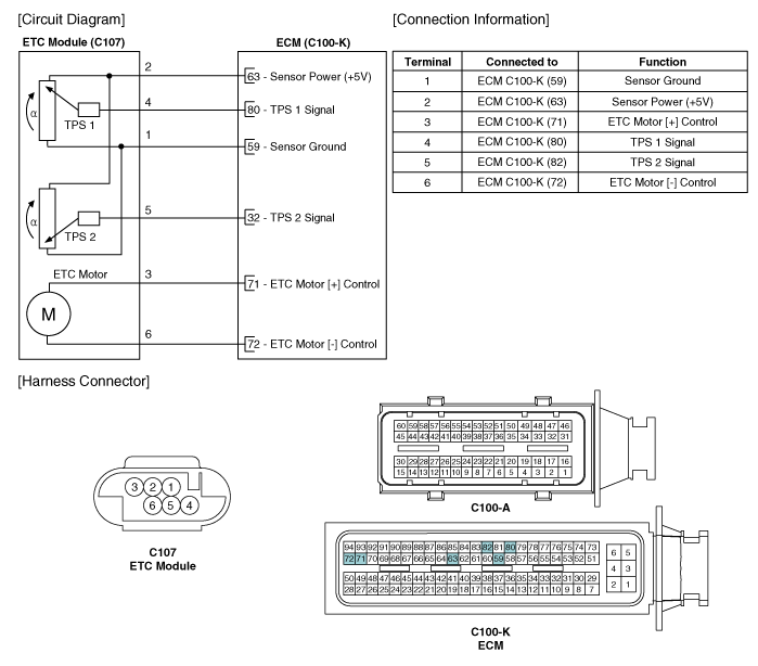
Kia Optima Hybrid: Engine Control System / ETC (Electronic Throttle Control) System Schematic Diagrams
| Circuit Diagram |

 ETC (Electronic Throttle Control) System Specifications
Specification [Throttle Position Sensor (TPS)] Throttle Angle(°)Output Voltage(V)TPS1TPS200.05.0100.484.52200.954.05301.433.57401.903.10502.382.62602.862.14703.331.67803.811.19904.290.711004.760.241055.00C.T ...
 ETC (Electronic Throttle Control) System Repair procedures
Inspection Throttle Position Sensor (TPS) 1. Connect the GDS on the Data Link Connector (DLC). 2. Start the engine and measure the output voltage of TPS 1 and 2 at C.T. and W.O.T. Throttle AngleOutput ...
Other information:
Kia Optima Hybrid (TF HEV) 2016-2020 Service Manual: Antenna Repair procedures
Inspection Glass Antenna Test 1. Wrap aluminum foil (A) around the tip of the tester probe (B) as shown. 2. Touch one tester probe to the glass antenna terminal (A) and move the other tester probe along the antenna wires to check that continuity exists. Glass Antenna Repair To make an effective ...
Kia Optima Hybrid (TF HEV) 2016-2020 Service Manual: NVLD(Natural Vacuum Leakage Detection) Repair procedures
Removal 1. Turn the ignition switch OFF and disconnect the battery negative (-) terminal. 2. Disconnect the NVLD connector (A). 3. Disconnect the ventilation hoses (B,C). 4. Remove the NVLD after by loosening the bolts (A). Installation • Install the component with the specified torques. • Note that ...
