Kia Optima Hybrid: Automatic Transaxle Control System / Components and Components Location
Kia Optima Hybrid (TF HEV) 2016-2020 Service Manual / Automatic Transaxle System / Automatic Transaxle Control System / Components and Components Location
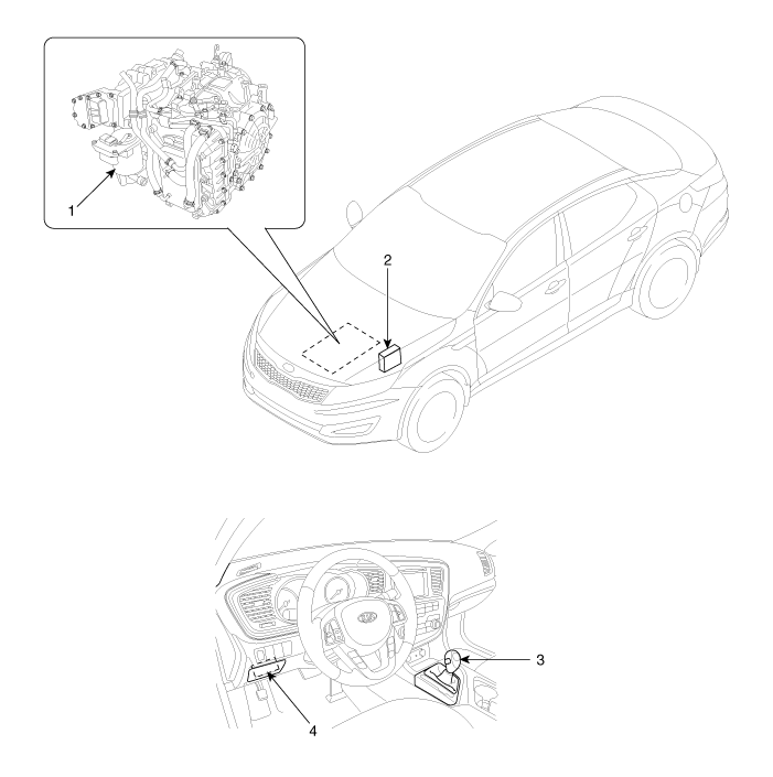
| Component Location |
[Vehicle Installation component]

| 1. Automatic transaxle 2. Transaxle control module (TCM) | 3. Shift lever 4. Data Link Connector (DLC) |
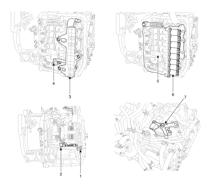
[Transaxle Installation component]

| 1. Input speed sensor 2. Output speed sensor 3. Solenoid valve connector 4. Oil temperature sensor | 5. Valve body assembly 6. Solenoid valve 7. Inhibitor switch |
 Schematic Diagrams
Circuit Diagram ...
 Transaxle Control Module (TCM) Description and Operation
Description Transaxle Control Module (TCM) is the automatic transaxle''s brain. The module receives and processes signals from various sensors and implements a wide range of transaxle controls to ensure ...
Other information:
Kia Optima Hybrid (TF HEV) 2016-2020 Service Manual: Head Lamps Repair procedures
Inspection 1. Check-points upon head lamp failure (HID) (1) Check the battery voltage. (Low beam will be on when the battery voltage above 9V.) (2) Check the fuse and relay. (3) Check the polarity of ballast. (If the polarity are changed, low beam doesn''t lighten) (4) Check the bulb connector securely. ...
Kia Optima Hybrid (TF HEV) 2016-2020 Service Manual: Brake Actuation Unit Components and Components Location
Components IBAU must not be disassembled. 1. ECU2. Reservoir3. Master cylinder Assembley 4. Valve block ...
© 2025 Copyright www.koptimatfhev.com
