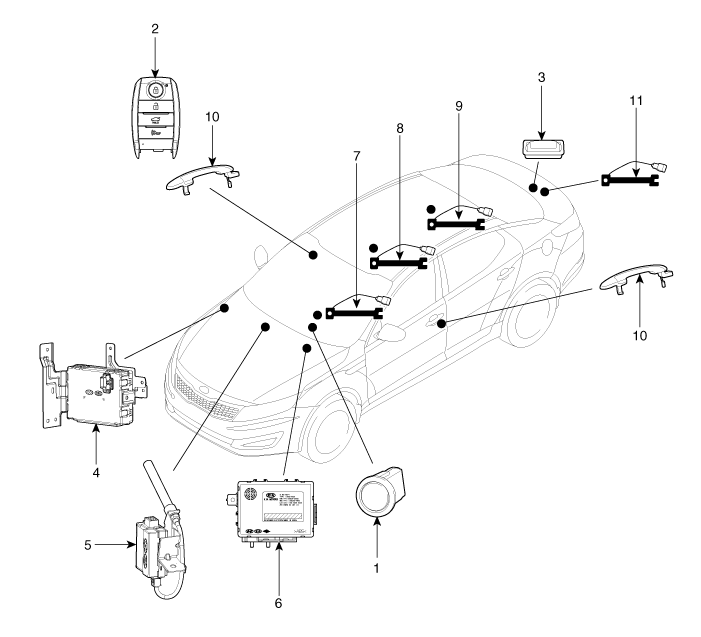
Kia Optima Hybrid: Button Engine Start System / Components and Components Location
Kia Optima Hybrid (TF HEV) 2016-2020 Service Manual / Body Electrical System / Button Engine Start System / Components and Components Location
| Component Location |

| 1. Start Stop Button(SSB) 2. FOB key 3. Trunk lid open switch 4. Smart key unit 5. RF receiver 6. Body control module | 7. Interior antenna 1 8. Interior antenna 2 9. Trunk antenna 10. Door handle & door antenna 11. Bumper antenna |
 Schematic Diagrams
Circuit Diagram (1) Circuit Diagram (2) ...
Other information:
Kia Optima Hybrid (TF HEV) 2016-2020 Service Manual: Front Body Body Repair
Front Body A Hood hinge mounting hole (O13)Fender apron upper inner panel tooling hole (O6.6)Front suspension mounting hole (O11)Cowl panel tooling hole (O8)Front pillar cornerFront pillar corner Front Body B Hood hinge mounting hole (O13)Fender apron upper inner panel tooling hole (O6.6)Engine mounting ...
Kia Optima Hybrid (TF HEV) 2016-2020 Service Manual: Front Lower Arm Repair procedures
Replacement 1. Remove the front wheel & tire. Tightening torque: 88.3 ~ 107.9N.m(9.0 ~ 11.0kgf.m, 65.1 ~ 79.6lb-ft) Be careful not to damage to the hub bolts when removing the front wheel & tire. 2. Loosen the bolt & nut and then remove the lower arm (A). Tightening torque: ...
© 2025 Copyright www.koptimatfhev.com

