Kia Optima Hybrid: Button Engine Start System / Schematic Diagrams
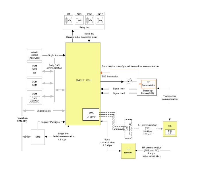
| Circuit Diagram (1) |

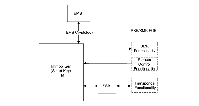
| Circuit Diagram (2) |

 Components and Components Location
Component Location 1. Start Stop Button(SSB)2. FOB key3. Trunk lid open switch4. Smart key unit5. RF receiver6. Body control module7. Interior antenna 18. Interior antenna 29. ...
 Description and Operation
Description System Overview The System offers the following features: – Human machine interface through a 1-stage button, for terminal switching and engine start. – Control of external relays for ACC ...
Other information:
Kia Optima Hybrid (TF HEV) 2016-2020 Service Manual: Rear Glass Defogger Printed Heater Repair procedures
Inspection Wrap tin foil around the end of the voltmeter test lead to prevent damaging the heater line. Apply finger pressure on the tin foil, moving the tin foil along the grid line to check for open circuits. 1. Turn on the defogger switch and use a voltmeter to measure the voltage of ...
Kia Optima Hybrid (TF HEV) 2016-2020 Service Manual: Passenger Airbag (PAB) Module Repair procedures
Removal 1. Disconnect the battery negative cable and wait for at least three minutes before beginning work. 2. Remove the glove box housing. (Refer to the Body group- crash pad). 3. Disconnect the passenger airbag connector (A) and remove the PAB mounting bolts (B). 4. Remove the crash pad. (Refer to ...
