Kia Optima Hybrid: Blind Spot Detection System / Blind Spot Detection Indicator Repair procedures
| Removal |
| 1. |
Disconnect the negative (-) battery terminal. |
| 2. |
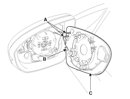
Remove the mirror (C) from the mirror holder after disconnecting the heater connector (A) and BSD warning connector (B).
|
| 3. |
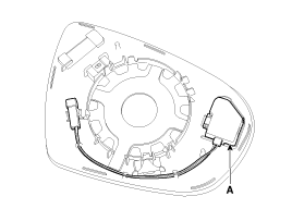
Remove the BSD warning lamp (A).
|
| Installation |
| 1. |
Install the BSD warning lamp and mirror. |
| 2. |
Connect the negative (-) battery terminal. |
| Inspection |
| 1. |
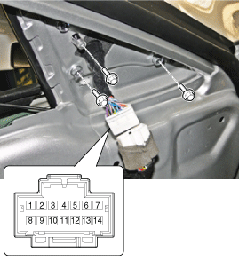
Verify that the mirror operates properly as shown in the below table.
BSD warning lamp
|
 Troubleshooting
Troubleshooting Examples of False-Alarm Occurrence from system characteristics (It’s not a problem) – Characteristics of EM Wave : EM Waves are reflected against all material and especially metal very ...
Other information:
Kia Optima Hybrid (TF HEV) 2016-2020 Service Manual: Description and Operation
Description Automatic transaxle system relies on various measurement data to determine the current control status and extrapolate the necessary compensation values. These values are used to control the actuators and achieve the desired control output. If a problem with the drivetrain, including the transaxle, ...
Kia Optima Hybrid (TF HEV) 2016-2020 Service Manual: Valve Clearance Adjustment
Valve Clearance Inspection And Adjustment Inspect and adjust the valve clearance when the engine is cold (Engine coolant temperature : 20°C (68°F)) and cylinder head is installed on the cylinder block. 1. Remove the cylinder head cover. (Refer to Timing system in this group) 2. Set No.1 ...


