Kia Optima Hybrid: Audio / Audio Remote Control Repair procedures
Kia Optima Hybrid (TF HEV) 2016-2020 Service Manual / Body Electrical System / Audio / Audio Remote Control Repair procedures
| Inspection |
| 1. |
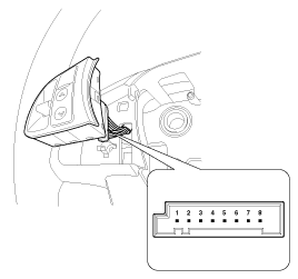
Check the audio remote control switch (A) for resistance between connector terminals in each switch position.
[LH-Audio]
[LH-Mute]
[Audio]
[Bluetooth + Voice]
[Mute + Trip + Reset]
|
| Removal |
| 1. |
Disconnect the negative (-) battery terminal. |
| 2. |
Remove the driver airbag module.
(Refer to the RT group) |
| 3. |
Remove the steering wheel.
(Refer to the ST group - "Steering column & shaft") |
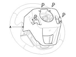
| 4. |
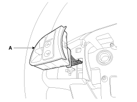
Remove the steering wheel cover (A) after loosening the screws.
|
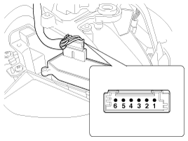
| 5. |
Remove the steering wheel remote control switch connector (A) after loosening the mounting screws.
[LH-Audio]
[LH-Mute]
|
| Installation |
| 1. |
Reassemble the steering wheel remote control switch after connecting the connector. |
| 2. |
Reassemble the steering wheel. |
| 3. |
Reassemble the driver airbag module.
|

 Audio Remote Control Schematic Diagrams
Circuit Diagram ...
 Multimedia jack Schematic Diagrams
Circuit Diagram ...
Other information:
Kia Optima Hybrid (TF HEV) 2016-2020 Service Manual: ATF Warmer Repair procedures
Removal 1. Remove the under cover (A). Tightening torque : 7.8 ~ 11.8N.m (0.8 ~ 1.2kgf.m, 5.8 ~ 8.7 lb-ft) 2. Drain the coolant of engine & transaxle cooling system. (Refer to Engine Mechanical System - "Coolant") 3. Remove the drain plug (A) and reinstall the drain plug after draining ATF totally. ...
Kia Optima Hybrid (TF HEV) 2016-2020 Service Manual: SS-B Solenoid Valve (ON/OFF) Specifications
Specifications ON/OFF Solenoid Valve(SS-A, SS-B) Control type : Normal low type Control pressure kpa(kgf/cm?, psi)490.33 (5.0, 71.12) Internal resistance(?)10 ~ 11 ...
© 2025 Copyright www.koptimatfhev.com