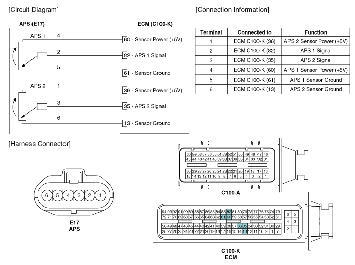
Kia Optima Hybrid: Engine Control System / Accelerator Position Sensor (APS) Schematic Diagrams
| Circuit Diagram |

 Accelerator Position Sensor (APS) Specifications
Specification AcceleratorPositionOutput Voltage (V)APS1APS2C.T0.7 ~ 0.80.29 ~ 0.46W.O.T3.85 ~ 4.351.93 ~ 2.18 ...
 Accelerator Position Sensor (APS) Repair procedures
Inspection 1. Connect the GDS on the Data Link Connector (DLC). 2. Turn the ignition switch ON. 3. Measure the output voltage of the APS 1 and 2 at C.T and W.O.T. AcceleratorPositionOutput Voltage (V)APS1APS2C.T0.7 ...
Other information:
Kia Optima Hybrid (TF HEV) 2016-2020 Service Manual: Specifications
Specification EngineT/MJoint typeMax. permissible angleOuterInnerOuterInnerGasoline 2.4M/TBJ#95TJ#9545°21°A/TBJ#95TJ#9545°21° Tightening torque ItemN.mkgf.mIb.ftFrontWheel nut88.2 ~ 107.89.0 ~ 11.065.0 ~ 79.5Driveshaft castle nut215.7 ~ 254.922.0 ~ 26.0159.1 ~ 188.0Strut assembly lower mounting bolt156.9 ...
Kia Optima Hybrid (TF HEV) 2016-2020 Service Manual: Electric A/C compressor Description and Operation
Description Through the development of electric compressors, fuel efficiency is improved and air conditioner can be implemented when the engine stopped.Operation Principle Compression Part One of the scrolls is fixed, while the other orbits eccen trically without self-rotating, thereby to trap and pump ...
