Kia Optima Hybrid: VESS(Virtual Engine Sound System) / Virtual Engine Sound System Unit Repair procedures
Kia Optima Hybrid (TF HEV) 2016-2020 Service Manual / Body Electrical System / VESS(Virtual Engine Sound System) / Virtual Engine Sound System Unit Repair procedures
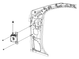
| Removal |
| 1. |
Disconnect the negative(-) battery terminal. |
| 2. |
Remove the glove box housing.
(Refer to the BD group - "Crash pad") |
| 3. |
Remove the VESS unit (A) with bracket after loosening the mounting nuts (2EA) and disconnecting the connector.
|
| Installation |
| 1. |
Install the VESS unit and connect the connector. |
| 2. |
Install the glove box housing. |
 Virtual Engine Sound System Unit Schematic Diagrams
Circuit Diagram ...
 Virtual Engine Sound Speaker Components and Components Location
Component Location ...
Other information:
Kia Optima Hybrid (TF HEV) 2016-2020 Service Manual: General Safety Information and Caution
Safety Precaution Since hybrid vehicles contain a high voltage battery, if the high voltage system or vehicles are handled incorrectly, this might lead to a serious accidents like electric shock and electric leakage. • Be sure to shut off the high voltage by removing the ...
Kia Optima Hybrid (TF HEV) 2016-2020 Service Manual: Engine Mounting Components and Components Location - Revised
Components 1. Engine mounting support bracket2. Engine mounting bracket3. Roll rod bracket4. Transaxle mounting bracket 5. Sub frame ...
© 2025 Copyright www.koptimatfhev.com