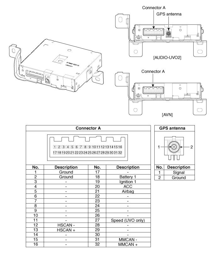
Kia Optima Hybrid: MTS System / Telemetics Unit (TMU) Components and Components Location
| Component |

| No. | Pin Name | Type | From | To | Description (Wiring Spec.) |
| 1 | GND | DC Ground | TMU | Battery | Connected to battery ground |
| 2 | GND | DC Ground | TMU | Battery | Connected to battery ground |
| 3 | - | - | - | - | - |
| 4 | - | - | - | - | - |
| 5 | - | - | - | - | - |
| 6 | - | - | - | - | - |
| 7 | - | - | - | - | - |
| 8 | - | - | - | - | - |
| 9 | - | - | - | - | - |
| 10 | - | - | - | - | - |
| 11 | - | - | - | - | - |
| 12 | HS CAN (-) | Data I/O | BUS | BUS | High Speed CAN bus low |
| 13 | HS CAN (+) | Data I/O | BUS | BUS | High Speed CAN bus high |
| 14 | - | - | - | - | - |
| 15 | - | - | - | - | - |
| 16 | - | - | - | - | - |
| 17 | - | - | - | - | - |
| 18 | Battery + | DC Input | Battery | TMU | DC level input from battery Supply power to TMU |
| 19 | Ignition 1 | Data Input | Junction Box | TMU | Vehicle Key mode status |
| 20 | ACC | Data Input | Junction Box | TMU | Vehicle Key mode status |
| 21 | Airbag | Data Input | ACU | TMU | Airbag status data from ACU |
| 22 | - | - | - | - | - |
| 23 | - | - | - | - | - |
| 24 | - | - | - | - | - |
| 25 | - | - | - | - | - |
| 26 | - | - | - | - | - |
| 27 | Speed | Data Input | - | TMU | GPS Calibration (UVO ONLY) |
| 28 | - | - | - | - | - |
| 29 | - | - | - | - | - |
| 30 | - | - | - | - | - |
| 31 | MM CAN (-) | Data I/O | BUS | BUS | Low Speed CAN bus low |
| 32 | MM CAN (+) | Data I/O | BUS | BUS | Low Speed CAN bus high |
 Description and Operation
Description The Vehicle Information System is a Telematics service that ensures comfortable and enjoyable driving by providing safety, security, and vehicle diagnostic information, with the option of using ...
 Telemetics Unit (TMU) Repair procedures
Removal • Take care not to scratch the crash pad and related parts. 1. Disconnect the negative (-) battery terminal. 2. Remove the AVN head unit. (Refer to AVN System - "AVN Head Unit") ...
Other information:
Kia Optima Hybrid (TF HEV) 2016-2020 Service Manual: Roof Trim Repair procedures
Replacement Sunvisor Replacement • Use a plastic panel removal tool to remove interior trim pieces to protect from marring the surface. • Put on gloves to protect your hands. 1. Loosen the mounting screws, then remove the sunvisor (A) and retainer (B). 2. Installation is the reverse ...
Kia Optima Hybrid (TF HEV) 2016-2020 Service Manual: AVN Head Unit Repair procedures
Removal AVN Head Unit • Take care not to scratch the center fascia panel and related parts. • Eject all the disc before removing the AVN head unit to prevent damaging the CD player''s load mechanism. 1. Disconnect the negative (-) battery terminal. 2. Using a screwdriver or remover, ...
