Kia Optima Hybrid: Smart key System / Smart key unit Components and Components Location
Kia Optima Hybrid (TF HEV) 2016-2020 Service Manual / Body Electrical System / Smart key System / Smart key unit Components and Components Location
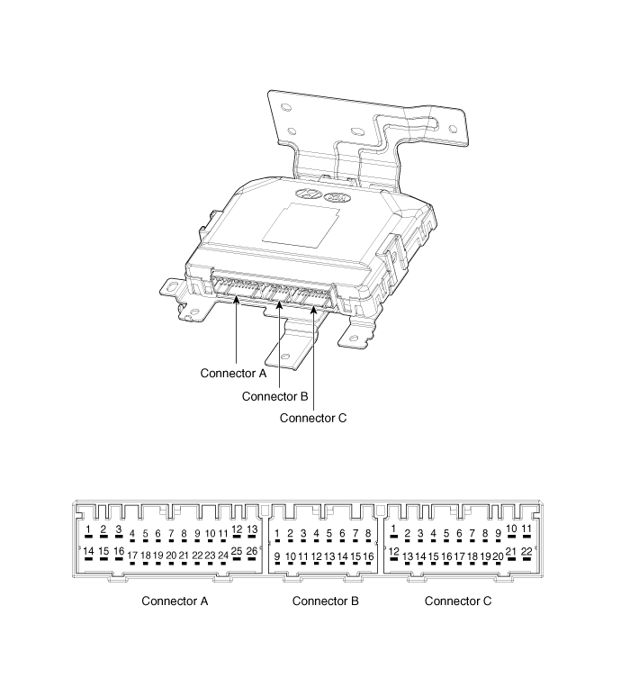
| Component (1) |

Connector Pin Information
| No. | Connector A (26pin) | Connector B (16pin) | Connector C (22pin) |
| 1 | V_BAT load | C_CAN low | SSB illumination ground |
| 2 | - | C_CAN high | Immobilzer indicator |
| 3 | Power ground1 | - | - |
| 4 | IGN1 | Stop lamp fuse | Interior antenna #2 power |
| 5 | IGN1 relay | Brake switch | Interior antenna #1 power |
| 6 | ACC | Immobilizer antenna power | - |
| 7 | IGN2 | - | - |
| 8 | SSB switch 2 | Wheel speed | Trunk antenna power |
| 9 | - | Driver toggle button | Bumper antenna power |
| 10 | RF COM | - | Assistant side antenna power |
| 11 | - | External buzzer | Driver side antenna power |
| 12 | B_CAN high | P position/ Clutch switch | SSB LED IGN |
| 13 | B_CAN low | Start feedback | SSB illumination power |
| 14 | V_BAT CPU | Immobilizer antenna ground | - |
| 15 | - | - | Interior antenna #2 ground |
| 16 | Power ground 2 | SSB LED ACC | Interior antenna #1 ground |
| 17 | Starter relay | ? | - |
| 18 | IGN2 relay | - | |
| 19 | ACC relay | Trunk antenna ground | |
| 20 | - | Bumper antenna ground | |
| 21 | - | Assistant side antenna ground | |
| 22 | - | Driver side antenna ground | |
| 23 | RPM | ? | |
| 24 | EMS COM | ||
| 25 | SSB switch 1 | ||
| 26 | Assistant toggle button |
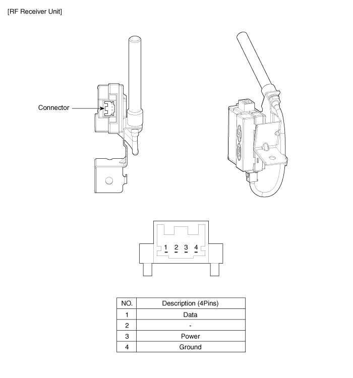
| Component (2) |

 Smart key Repair procedures
Smart Key Smart Key Code Saving 1. Connect the DLC cable of GDS to the data link connector in driver side crash pad lower panel, turn the power on GDS. 2. Select the vehicle model and then do "Smart key ...
 Smart key unit Schematic Diagrams
Circuit Diagram ...
Other information:
Kia Optima Hybrid (TF HEV) 2016-2020 Service Manual: General Safety Information and Caution
Safety Precaution Since hybrid vehicles contain a high voltage battery, if the high voltage system or vehicles are handled incorrectly, this might lead to a serious accidents like electric shock and electric leakage. • Be sure to shut off the high voltage by removing the ...
Kia Optima Hybrid (TF HEV) 2016-2020 Service Manual: Active Air Flap(AAF) Schematic Diagrams
Schematic Diagram Circuit Diagram ...
© 2025 Copyright www.koptimatfhev.com
