Kia Optima Hybrid: Rear Suspension System / Rear Assist Arm Repair procedures
| Replacement |
| 1. |
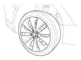
Remove the rear wheel & tire.
|
| 2. |
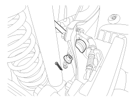
Remove the sprit pin and castle nut and then disconnect the rear assist arm (A) from the rear axle.
|
| 3. |
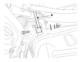
Loosen the bolt & nut and then remove the rear assist arm (A) from the sub frame.
|
| 4. |
Installation is the reverse of removal. |
| Inspection |
| 1. |
Check the bushing for wear and deterioration. |
| 2. |
Check for all bolts and nut. |
 Rear Stabilizer Bar Repair procedures
Replacement 1. Remove the rear wheel & tire. Tightening torque: 88.3 ~ 107.9N.m (9.0 ~ 11.0kgf.m, 65.1 ~ 79.6lb-ft) Be careful not to damage the hub bolts when removing the rear wheel ...
 Trailing Arm Repair procedures
Replacement 1. Remove the rear wheel & tire. Tightening torque: 88.3 ~ 107.9N.m (9.0 ~ 11.0kgf.m, 65.1 ~ 79.6lb-ft) Be careful not to damage the hub bolts when removing the rear wheel ...
Other information:
Kia Optima Hybrid (TF HEV) 2016-2020 Service Manual: Seat Track Position Sensor (STPS) Description and Operation
Description The STPS operates via a non-contacting magnetic proximity sensing device combined with a simple electronic circuit resulting in the ability of producing two separate and distinct logic level signals. The STPS output signal is altered by the proximity of a separate ferro-magnetic shunt, which ...
Kia Optima Hybrid (TF HEV) 2016-2020 Service Manual: Repair procedures
High Voltage Shutoff Procedure Shut off the high voltage circuit before doing any work related with the high voltage system (Battery Pack Assembly, Power Relay Assembly, HPCU, BMS ECU, Hybrid Drive Motor, Inverter, HSG, LDC Power Cable, Electric Compressor, and so on). 1. Turn the ignition ...


