Kia Optima Hybrid: AHB(Active Hydraulic Boost) System / Pressure Source Unit Repair procedures
| Removal |
| 1. |
Turn ignition switch OFF and disconnect the negative (-) battery cable. |
| 2. |
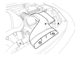
Remove the air duct (A).
|
| 3. |
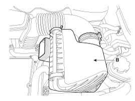
Remove air cleaner assembly (B).
|
| 4. |
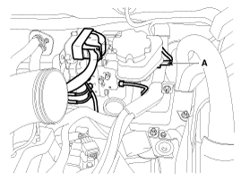
Disconnect the brake fluid level switch connector (A), and remove the reservoir cap.
|
| 5. |
Remove the brake fluid from the reservoir with a syringe.
|
| 6. |
Remove the IBAU (Refer to the AHB system - Intergrated Brake Actuation Unit (IBAU)) |
| 7. |
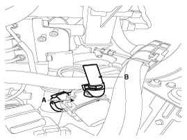
Disconnect the connector (A) and after removing a mounting clip, disconnect the reservoir hose(B).
|
| 8. |
Disconnect the brake tube from the PSU by loosening the bolt (B).
|
| 9. |
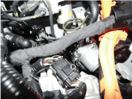
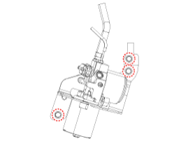
After disconnecting a connecter, Loosen the PSU bracket bolts and remove the PSU.
|
| Installation |
| 1. |
Installation is the reverse of removal. |
| 2. |
Check the brake pedal operation. |
| 3. |
After filling the brake fluid in the reservoir, perform the air bleed. (Refer to the AHB system - AHB system air bleeding) |
| 4. |
Conduct calibration after removing the brake pedal assembly. (Refer to the brake pedal - calibration) |
| 5. |
Tighten the PSU bracket bolts and brake tube to the specified torque. |
| 6. |
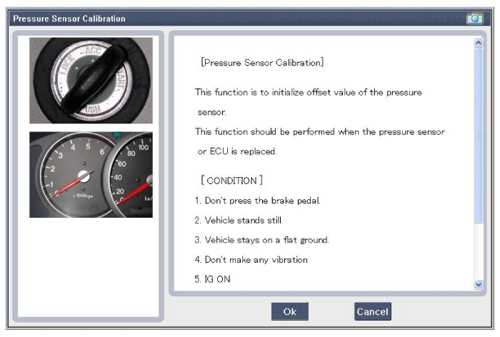
Conduct calibration after removing or installing the PSU. |
| 1. |
Connect the GDS. (CAN line or OBD connector) |
| 2. |
Turn ignition switch on. |
| 3. |
Press calibration button of the pressure sensor. |
| 4. |
Pressure sensor calibration procedure is performed. (Calibration records, DTC codes erasure)
|
| 5. |
Turn ignition switch off and on after calibration procedure. |
| 6. |
Confirm success of calibration. |
 Pressure Source Unit Components and Components Location
Components PSU must not be disassembled. 1. Motor connecter2. Bracket3. Block4. Accumulator5. Damper6. Motor ...
 Brake Line Components and Components Location
Components ...
Other information:
Kia Optima Hybrid (TF HEV) 2016-2020 Service Manual: Thermostat Repair procedures
Removal and Installation Disassembly of the thermostat would have an adverse effect, causing a lowering of cooling efficiency. Do not remove the thermostat, even if the engine tends to overheat. 1. Drain engine coolant so its level is below thermostat. 2. Disconnect the radiator lower hose ...
Kia Optima Hybrid (TF HEV) 2016-2020 Service Manual: TPMS Sensor Repair procedures
Removal Tire Removal 1. Deflate tire & remove balance weights. • The tire bead should be broken approx. 90° from the valve side of the wheel. The bead breaker should not be set too deep. • Avoid tire/tool contact with the valve on dismount. • Dismount should end near the valve. ...

