Kia Optima Hybrid: Air Conditioning System / Photo Sensor Repair procedures
| Inspection |
| 1. |
Ignition "ON" |
| 2. |
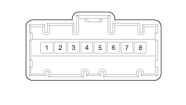
Using the scan tool. |
| 3. |
Emit intensive light toward photo sensor using a lamp, and check the output voltage change. |
| 4. |
The voltage will rise with higher intensive light and reduce with lower intensive light.
|
| Replacement |
| 1. |
Disconnect the negative (-) battery terminal. |
| 2. |
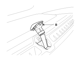
With the (-) driver, remove the photo sensor (A) from the center of defrost nozzle.
|
| 3. |
Install in the reverse order of removal. |
 Photo Sensor Description and Operation
Description 1. The photo sensor is located at the right of defrost nozzle. 2. The photo sensor contains a photovoltaic (sensitive to sunlight) diode. The solar radiation received by its light receiving ...
 Ambient Sensor Description and Operation
Description 1. The ambient temperature sensor is located at the front of the condenser and detects ambient air temperature. It is a negative type thermistor; resistance will increase with lower temperature, ...
Other information:
Kia Optima Hybrid (TF HEV) 2016-2020 Service Manual: Electric Oil Pump (EOP) Components and Components Location
Component Location 1. Electric Oil Pump (EOP)2. Automatic transaxle ...
Kia Optima Hybrid (TF HEV) 2016-2020 Service Manual: High Voltage Shut-off Procedures
High Voltage Shut-off Procedures Be sure to read and follow the “General Safety Information and Caution” before doing any work related with the high voltage system. Failure to follow the safety instructions may result in serious electrical injuries. • High voltage components: ...


